K2 Build Log Part Six: Gantry Motors and Idlers
Mar 16, 2022Let’s build the gantry motors and idlers. There are two versions: Short Motor, Tall Idler and Tall Motor, Short Idler.
Tall Motor, Short Idler
BOM
- 1x Printed parts (mind you get the right accent part, the “ears” are slightly shorter)
- 1x Printed pulley alignment jig
- 1x Motor (missing from the picture below)
- 2x 12mm pulleys
- 2x 625 bearings
- 6x M4 heatsets
- 1x M5x35 shaft (missing from the picture below)
- 2-3x M5 washers
- 4x M3x10 SHCS
- 2x M4x20 SHCS
- 4x M4x50 SHCS
- 4x M4x55 SHCS
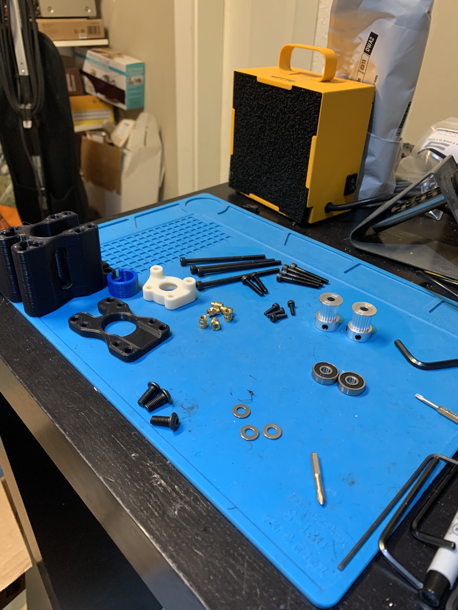
Figure 1: Gantry Tall Motor, Short Idler BOM
Aligning the motor pulley
Place the pulley in the jig with the hub down:
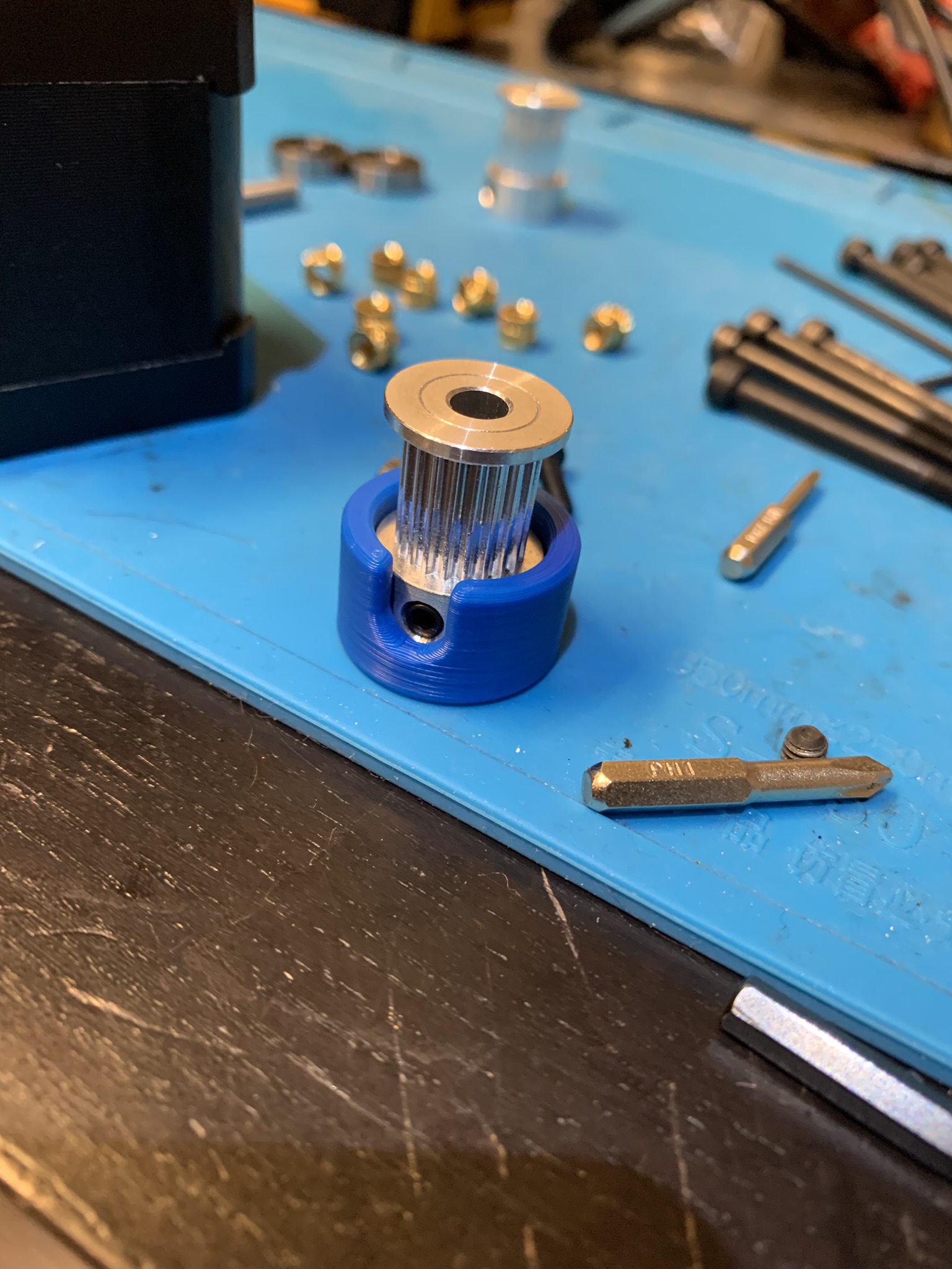
Figure 2: Pulley inside alignment jig
Insert the motor shaft into the pulley with the flat aligned to one of the set screws. Move the pulley and jig up and down till the nub inside the jig is fully inside the pulley’s channel. I found it easier with the whole thing inverted. Once you’re satisfied, tighten the set screws.
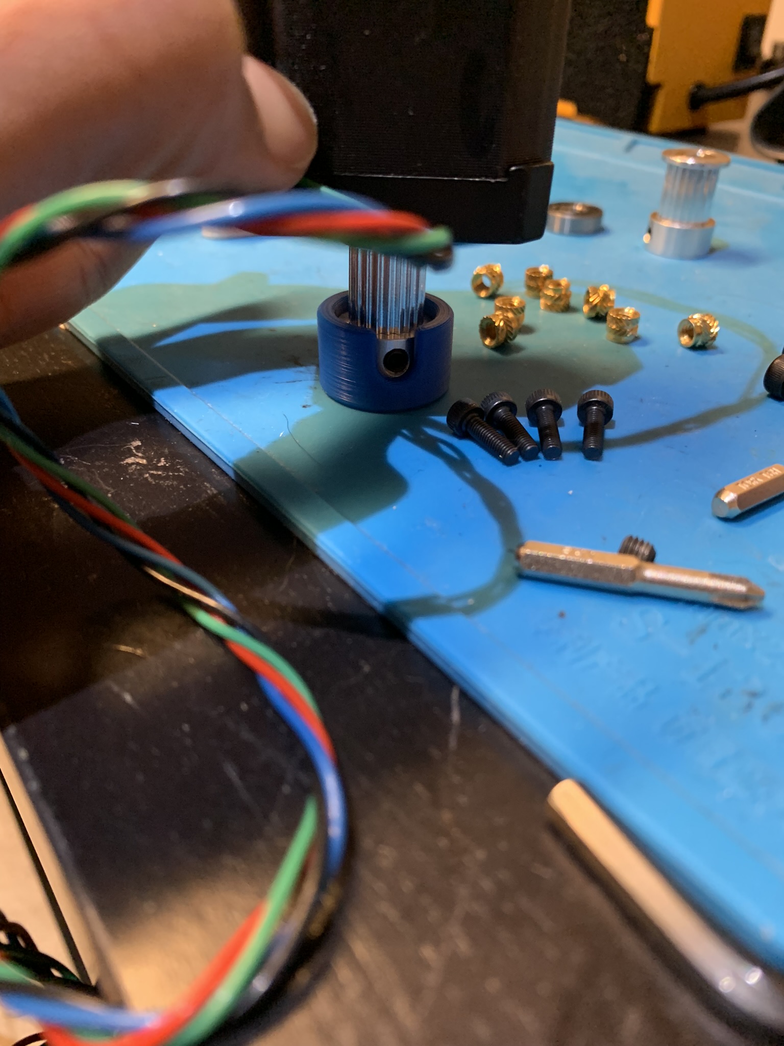
Figure 3: Pulley aligned on motor
Now remove one set screw at a time, apply loctite and screw it back in. Place the printed part on top with the flat side on the motor and align it according to how you want the wires to end up. I aligned mine so that the wires would go towards the nearest side of the printer when installed. Apply loctite to 4x M3x10 SHCS and screw the printed part to the motor.
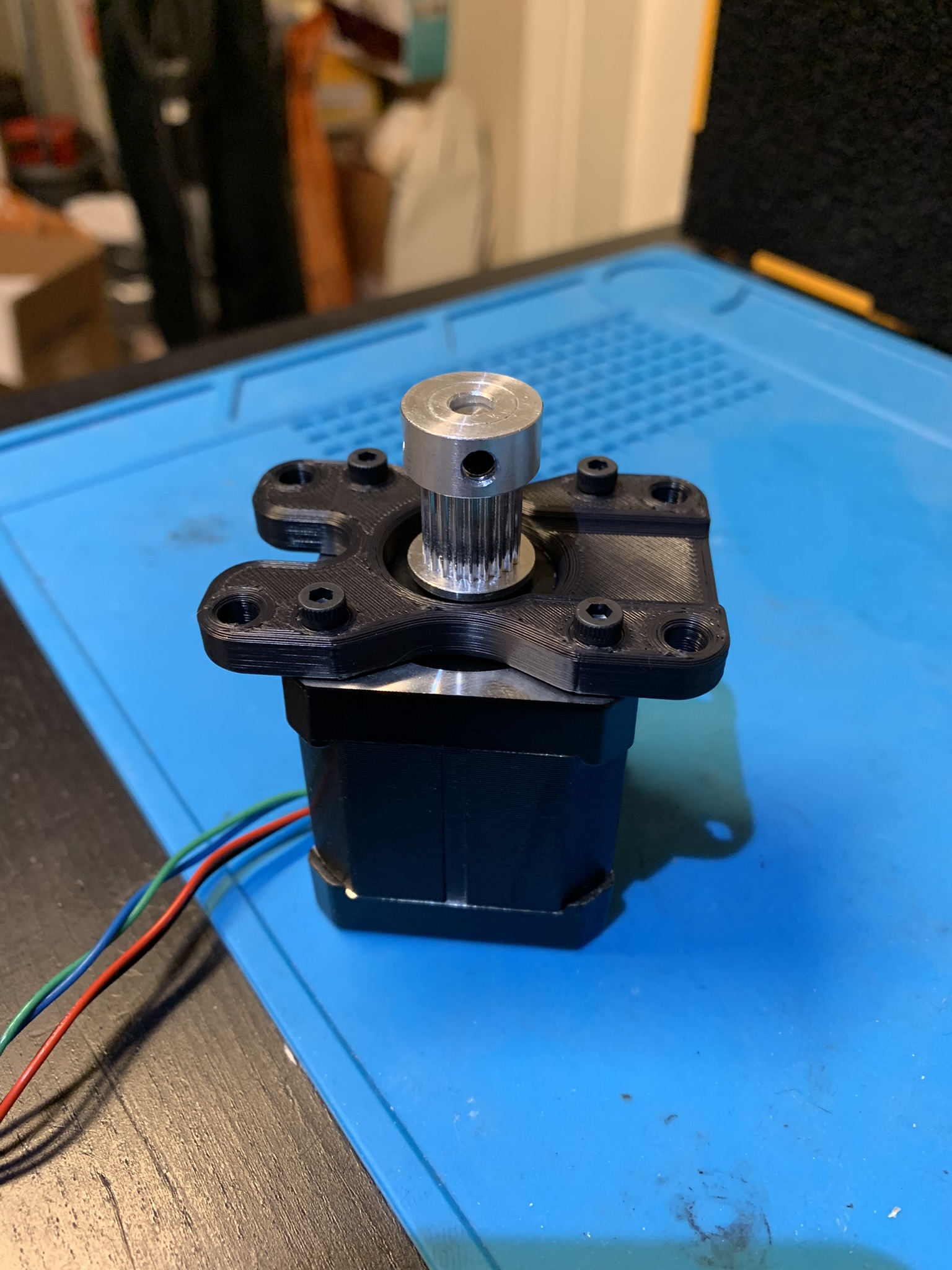
Figure 4: Printed part attached to motor
Idler stack
For the following instructions, I’m assuming that you aren’t using shaft retaining compound to “weld” the pulley to the motor. If you are, you can skip everything after the pulley is aligned since you won’t be needing flats or set screws.
Remove one of the set screws from a pulley. Insert the pulley onto the M5x35 shaft, aligning the set screw hole with the flat on the shaft. Build the rest of the idler stack as follows around the M5x35 shaft:
Bearing - Washer - Pulley with hub down - Washer - Washer - Bearing
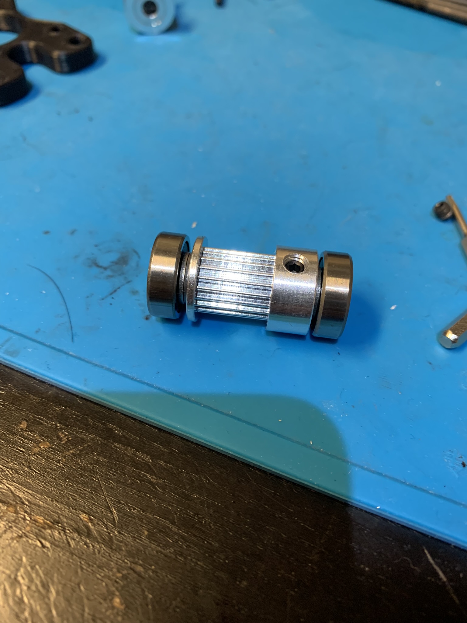
Figure 5: Idler stack
Note that the second washer above the pulley isn’t in the eDrawing. That’s because the spacing for the idler pulley is designed to allow some leeway for non-standard rails sizes. However, this results in the top pulley not being fully seated in the accent part. In order to seat the pulley fully for my standard-sized Robotdigg rails, I added an extra washer.
Use a sharpie through the set screw hole to make a mark on the shaft. Remove the shaft from the stack and use a dremel to grind a flat around the mark you made. This flat will help the set screw remain immobile and prevent the pulley from rotating relative to the shaft.
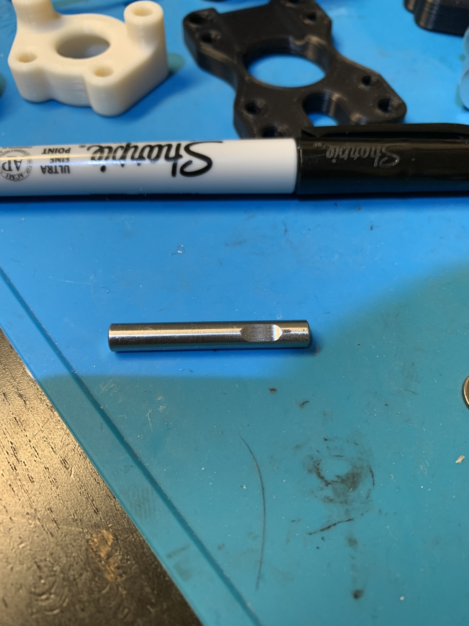
Figure 6: Idler shaft with ground flat
Rebuild the idler stack and insert it into the bearing hole in the main printed part. Place the accent part on top and press it down till its flush with the main part.
Installing the main body
Insert 4x M4 roll-in nuts (lower in the top extrusion) and 3x M5 roll-in nuts (left in the bottom extrusion) approximately in the locations shown:
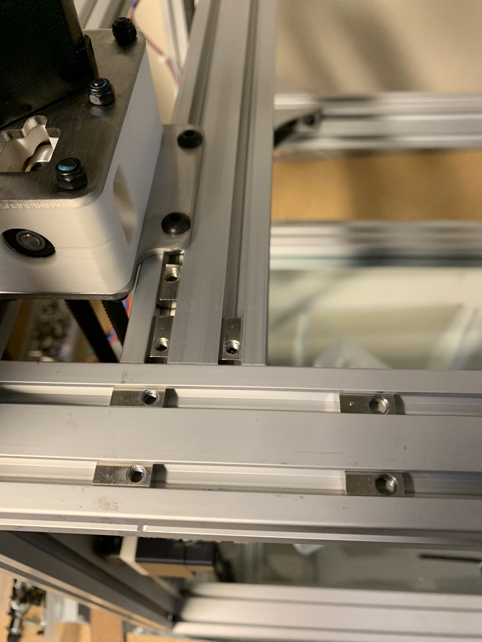
Figure 7: Roll-in nuts
For subsequent steps, apply loctite to each bolt.
Insert 2x M4x20 SHCS into the holes shown:
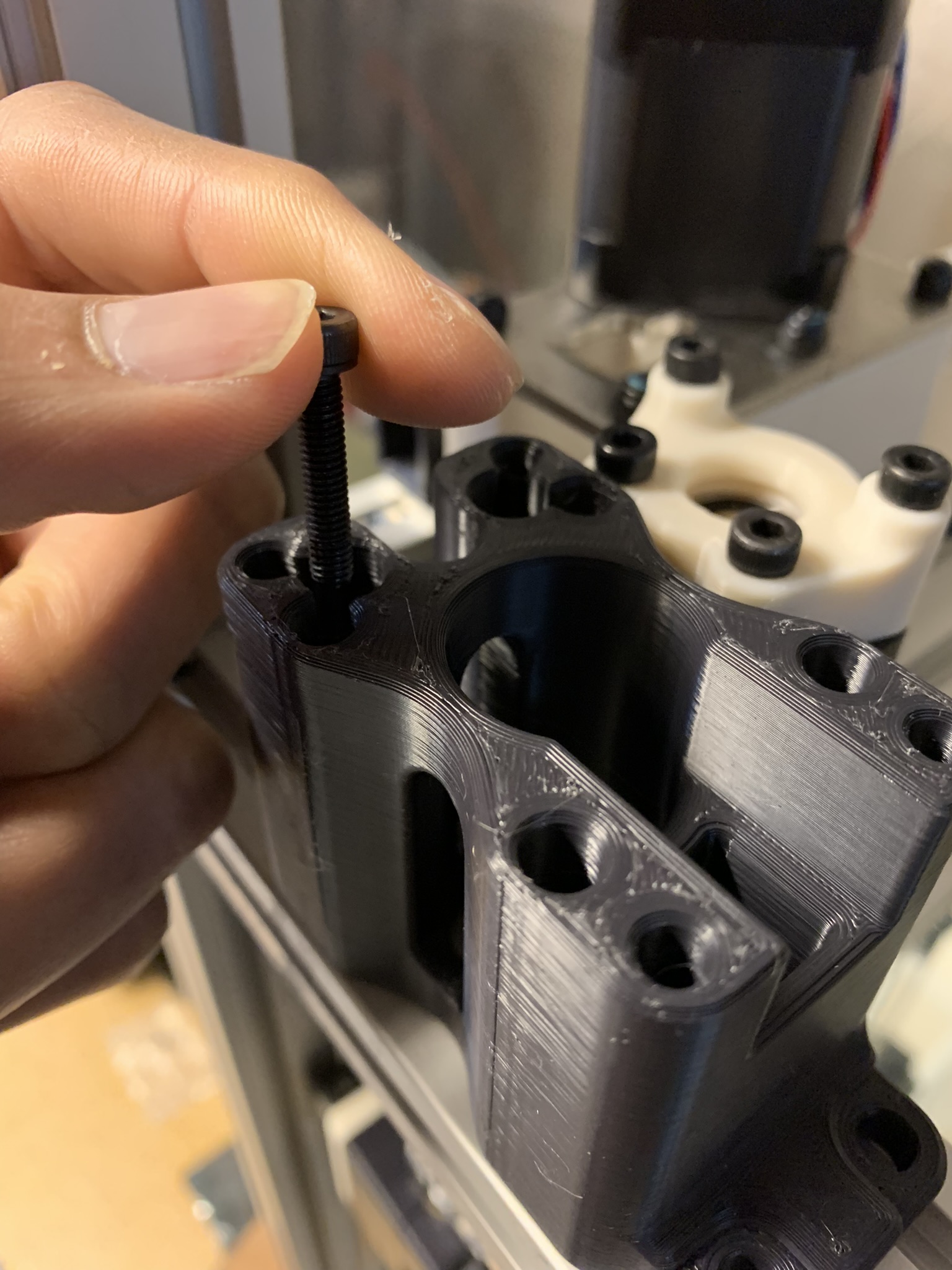
Figure 8: First M4x20 bolt
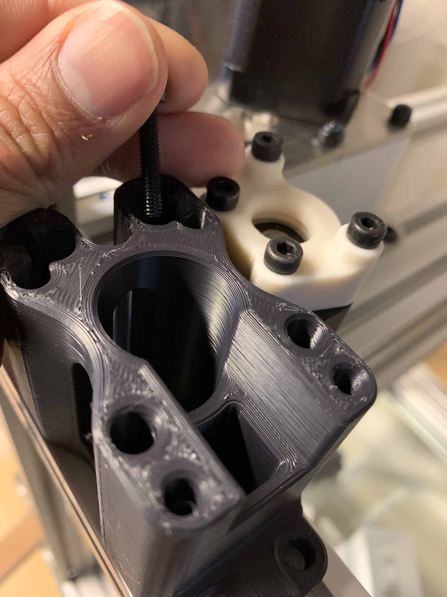
Figure 9: Second M4x20 bolt
Insert 2x M5x12 BHCS (eDrawing says M5x10 but I found them too short) into the front holes:
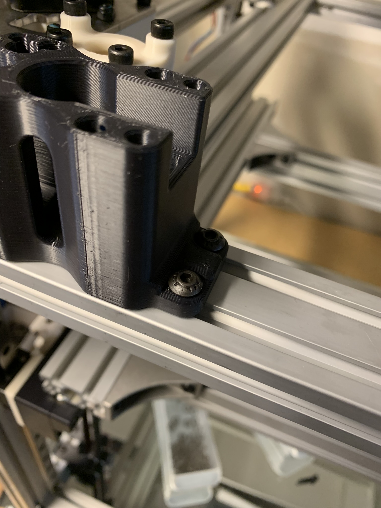
Figure 10: Front M5x12 bolts
Insert 1x M5x12 BHCS into the side hole:
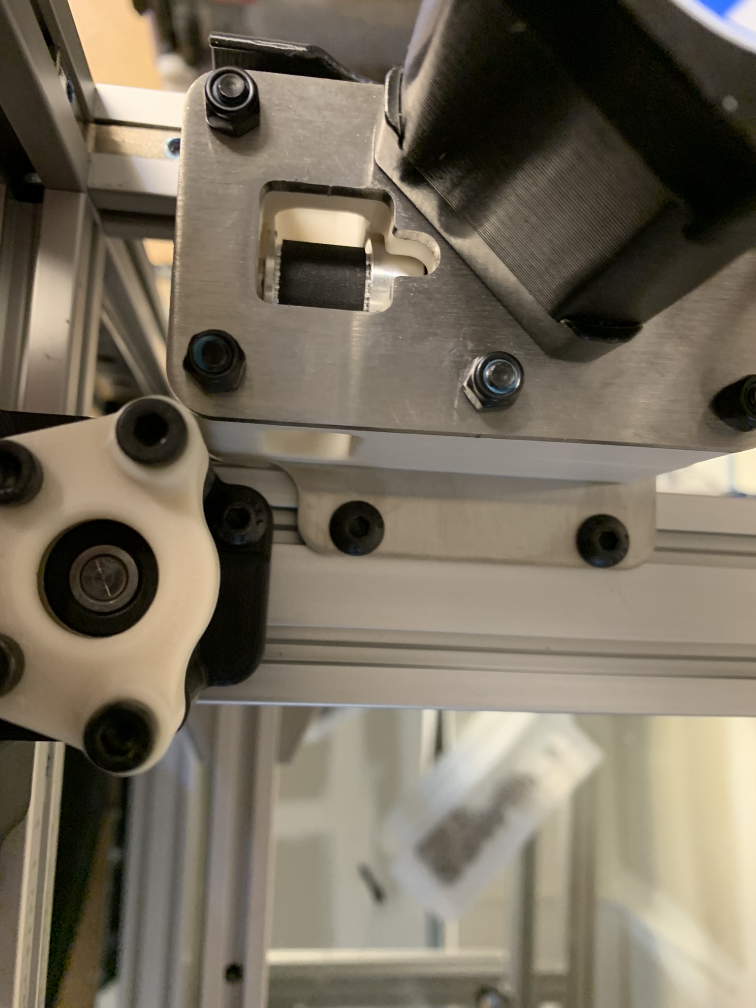
Figure 11: Rear M5x12 bolt
Insert 4x M4x50 SHCS into the idler accent part:
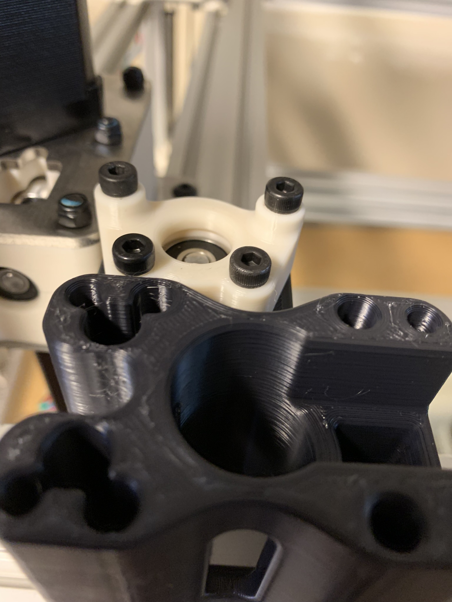
Figure 12: Idler bolts
Using calipers and a flat surface, ensure that the body is 45mm from the Z extrusion and flat with the front extrusion:
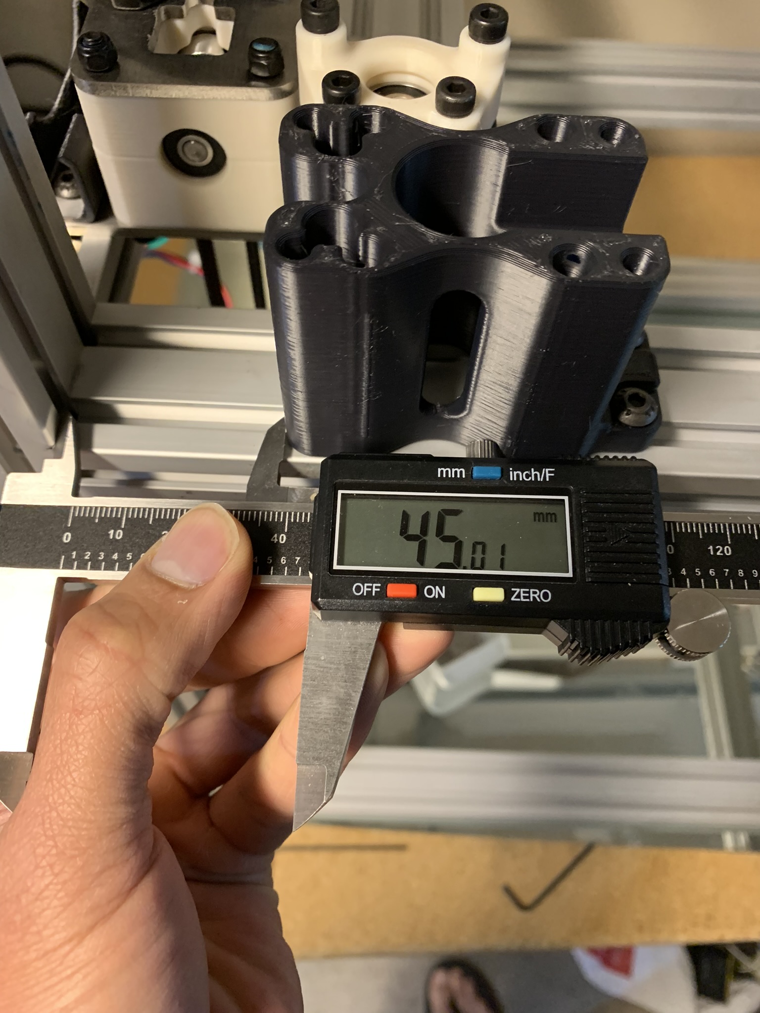
Figure 13: Left alignment
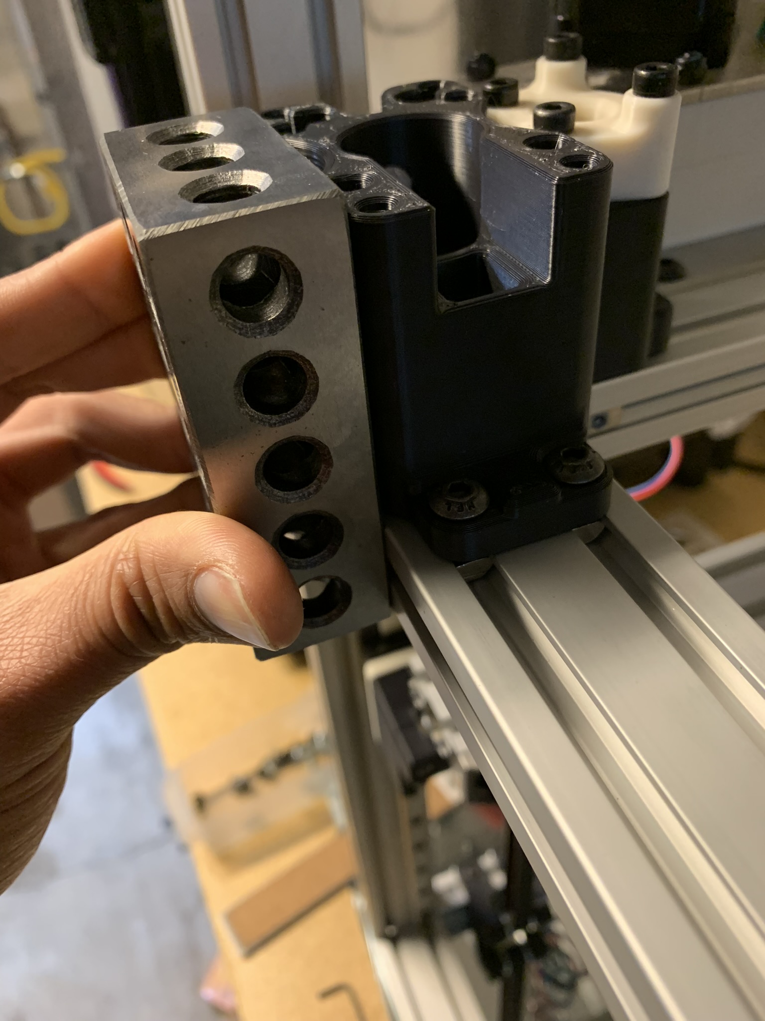
Figure 14: Front alignment
Tighten all bolts.
Installing the motor
Place the motor with its attached plate on top of the main body.

Figure 15: Motor placed on top
Insert 4x M4x55 SHCS and tighten them.

Figure 16: Finished installation
Short Motor, Tall Idler
BOM
- 1x Printed parts (the accent part has longer “ears”)
- 1x Printed pulley alignment jig
- 1x Motor
- 2x 12mm pulleys
- 2x 625 bearings
- 6x M4 heatsets
- 1x M5x35 shaft
- 2-3x M5 washers
- 3x M3x10 SHCS
- 2x M4x20 SHCS (missing from the picture below)
- 4x M4x30 SHCS
- 4x M4x70 SHCS
- 3x M5x12 BHCS (missing from the picture below)
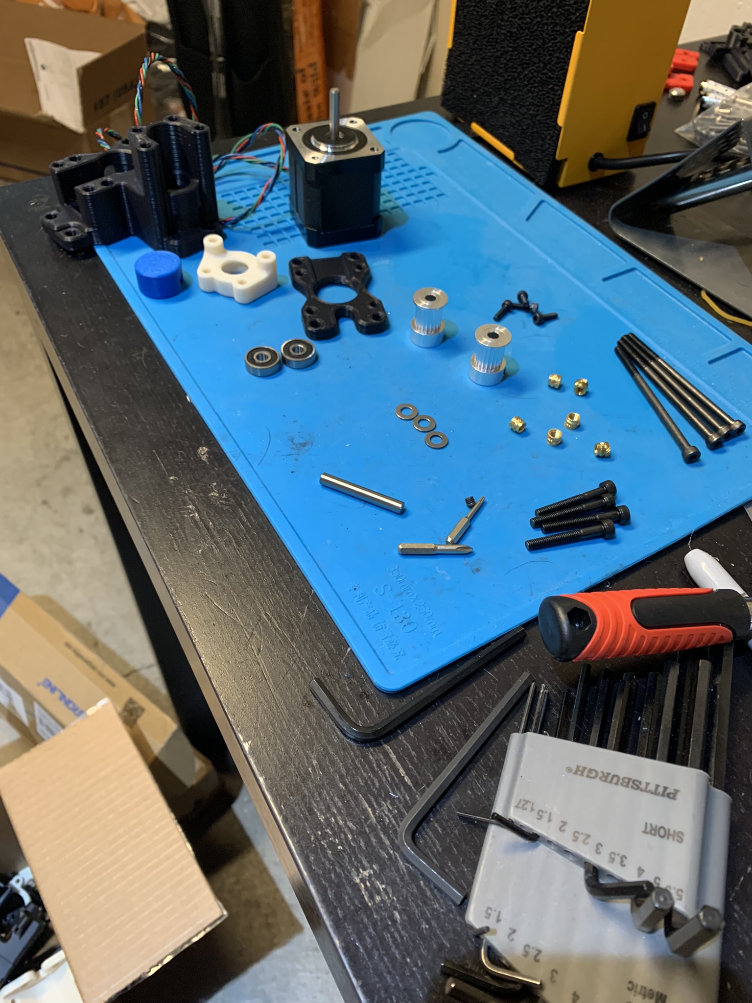
Figure 17: Gantry Short Motor, Tall Idler BOM
Heatsets
Insert the heatsets into the holes in the picture below:
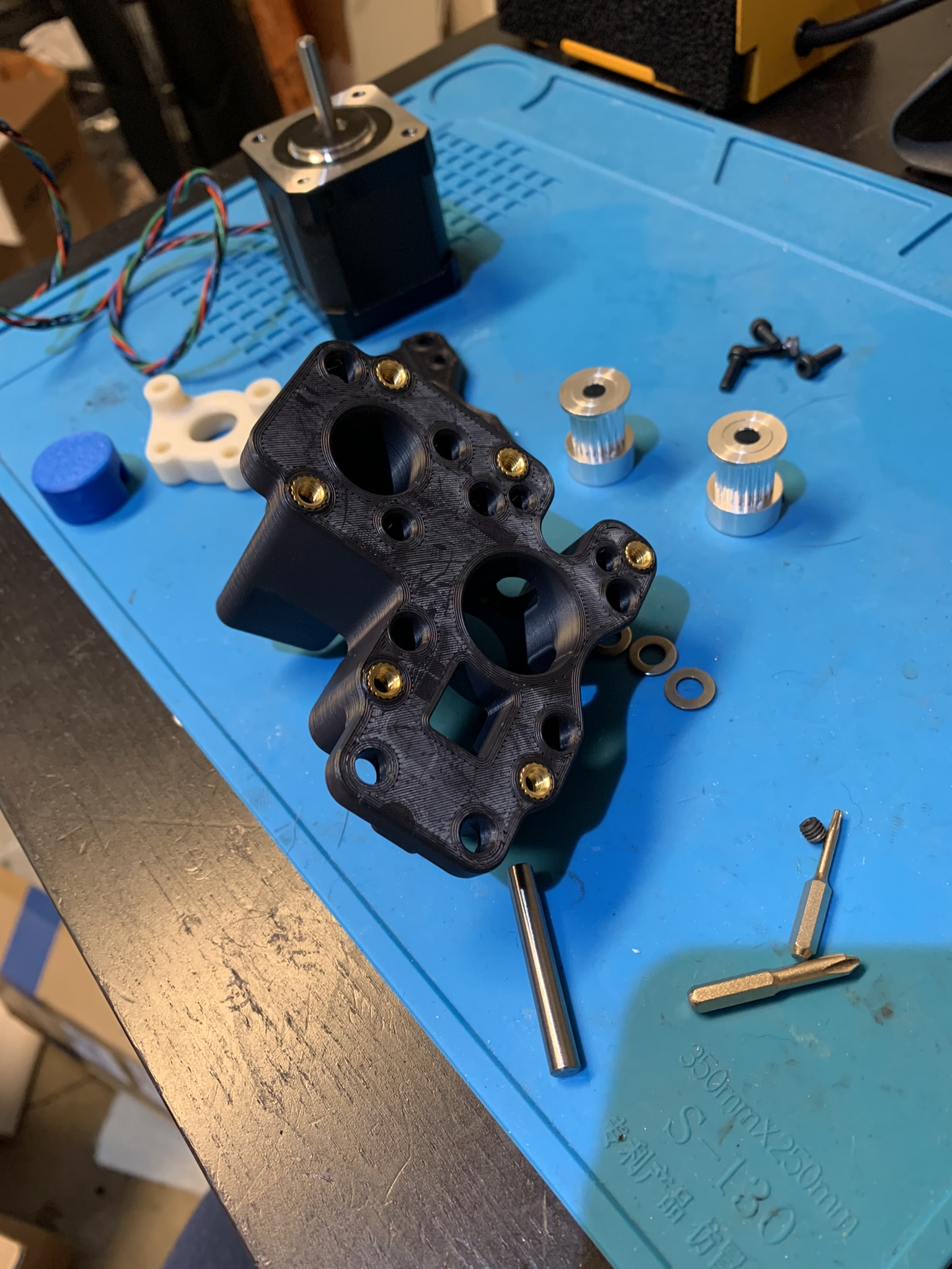
Figure 18: Gantry Short Motor, Tall Idler BOM
Motor and Idler stack
Same as described above
Installing the main body
Insert 4x M4 roll-in nuts (the ones on the right in the lower extrusion) and 3x M5 roll-in nuts (the remaining ones) approximately in the locations shown:
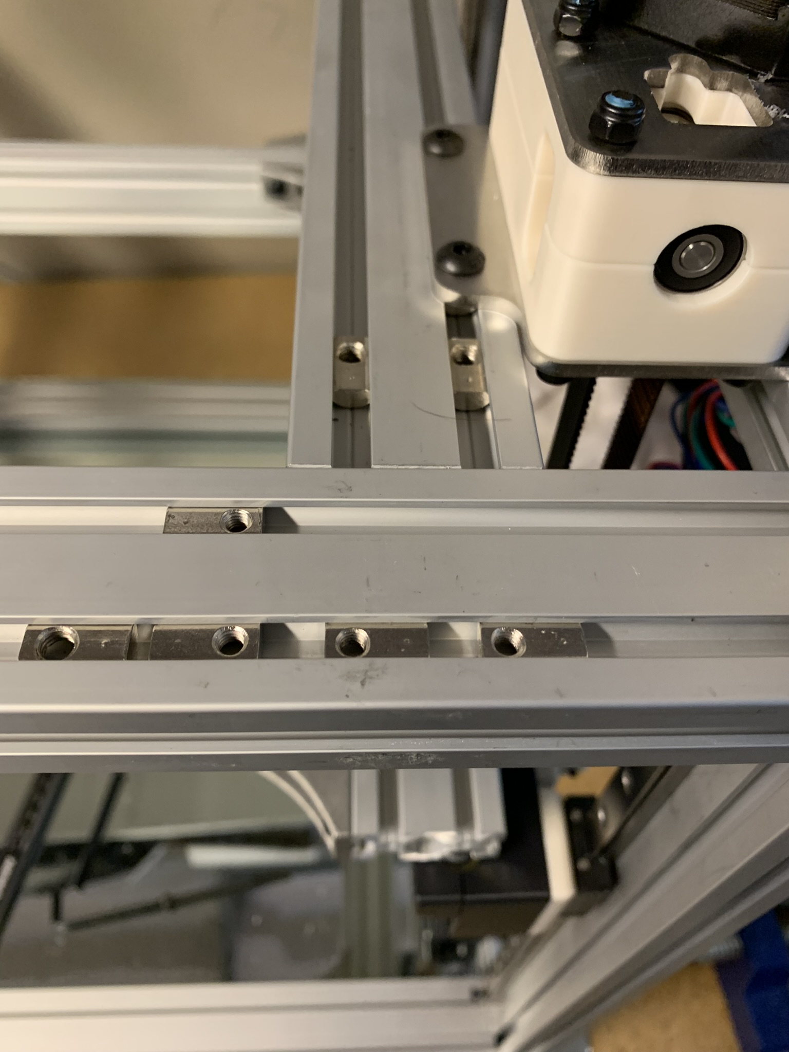
Figure 19: Roll-in nuts
Place the main body in position and insert bolts in locations analogous to the previous assembly. The only difference is that the idler will use 4x M4x70 SHCS.
Align it so that it is 45mm from the Z extrusion and flat with the front extrusion.
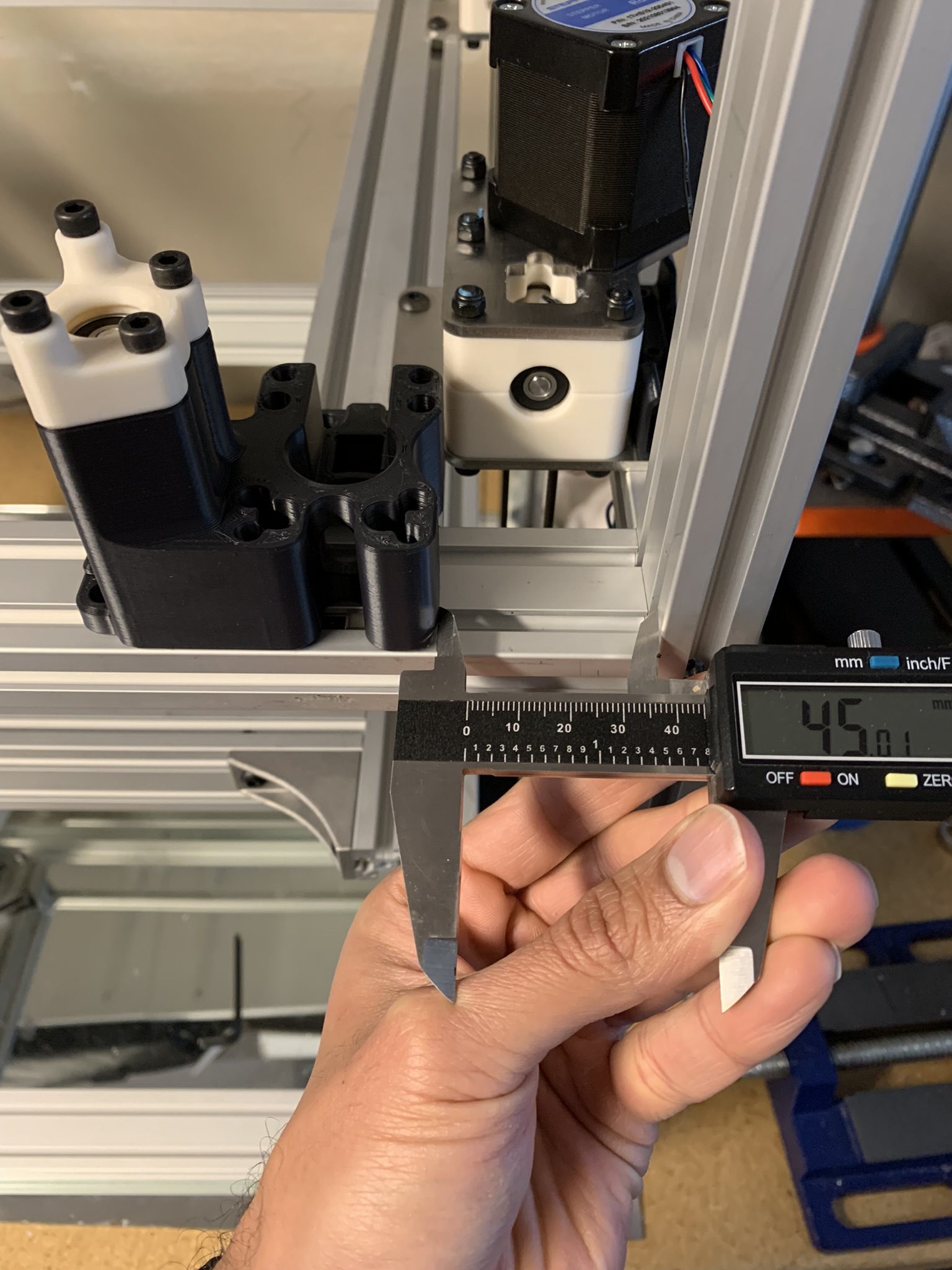
Figure 20: Right alignment
Installing the motor
Place the motor assembly on top and secure it with 4x M4x30 SHCS.
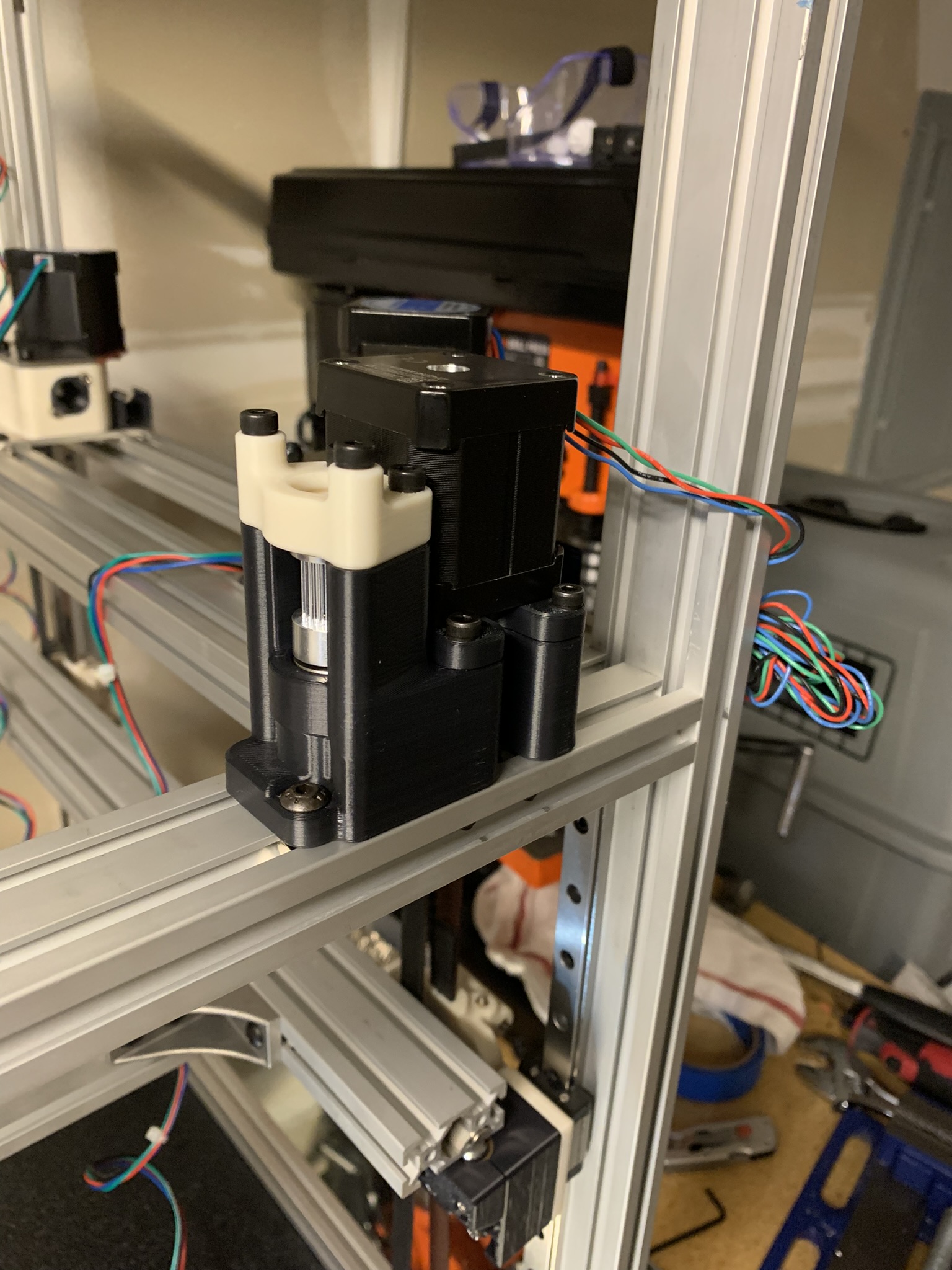
Figure 21: Finished installation
Remaining two motor assemblies
Repeat the above process, the remaining two are identical to the ones we just built and installed.
Gantry rails
Place one of your gantry rails between the two motor parts we just installed and verify that it fits. If your rail doesn’t fit, check the distances of your motor parts from the vertical extrusions again. If they’re still 45mm, hop on the Annex discord and ask for help.
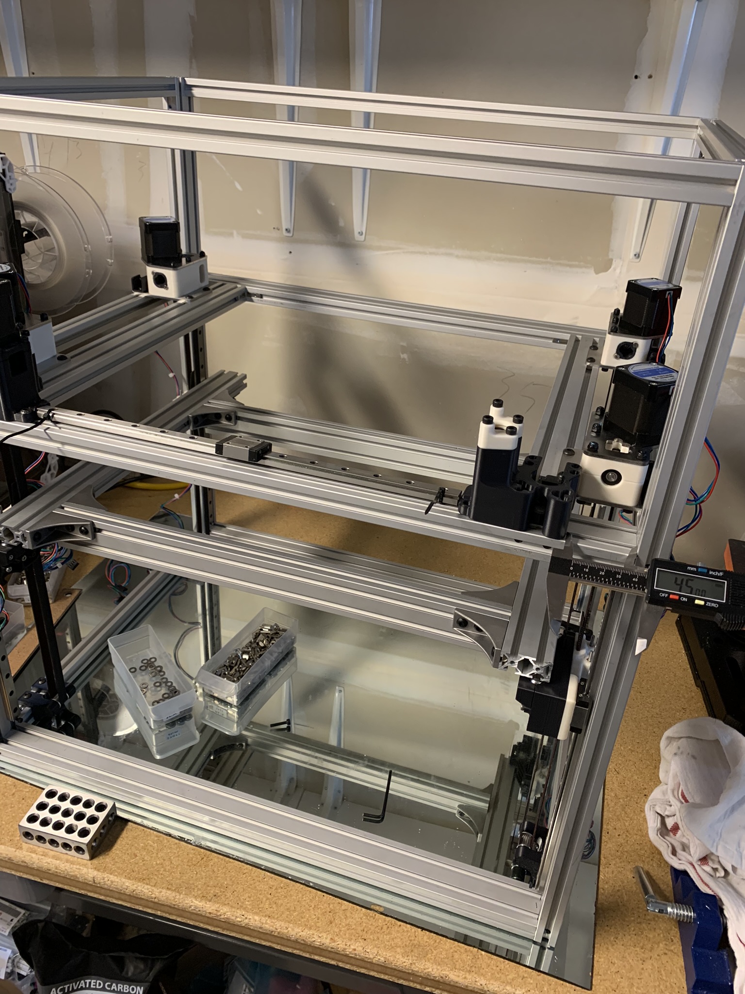
Figure 22: Finished assembly on the front side of the gantry, rail test fit
Using the same method as described in part two, install the rail onto the inner slot of the extrusion. Repeat this process for the remaining three rails.
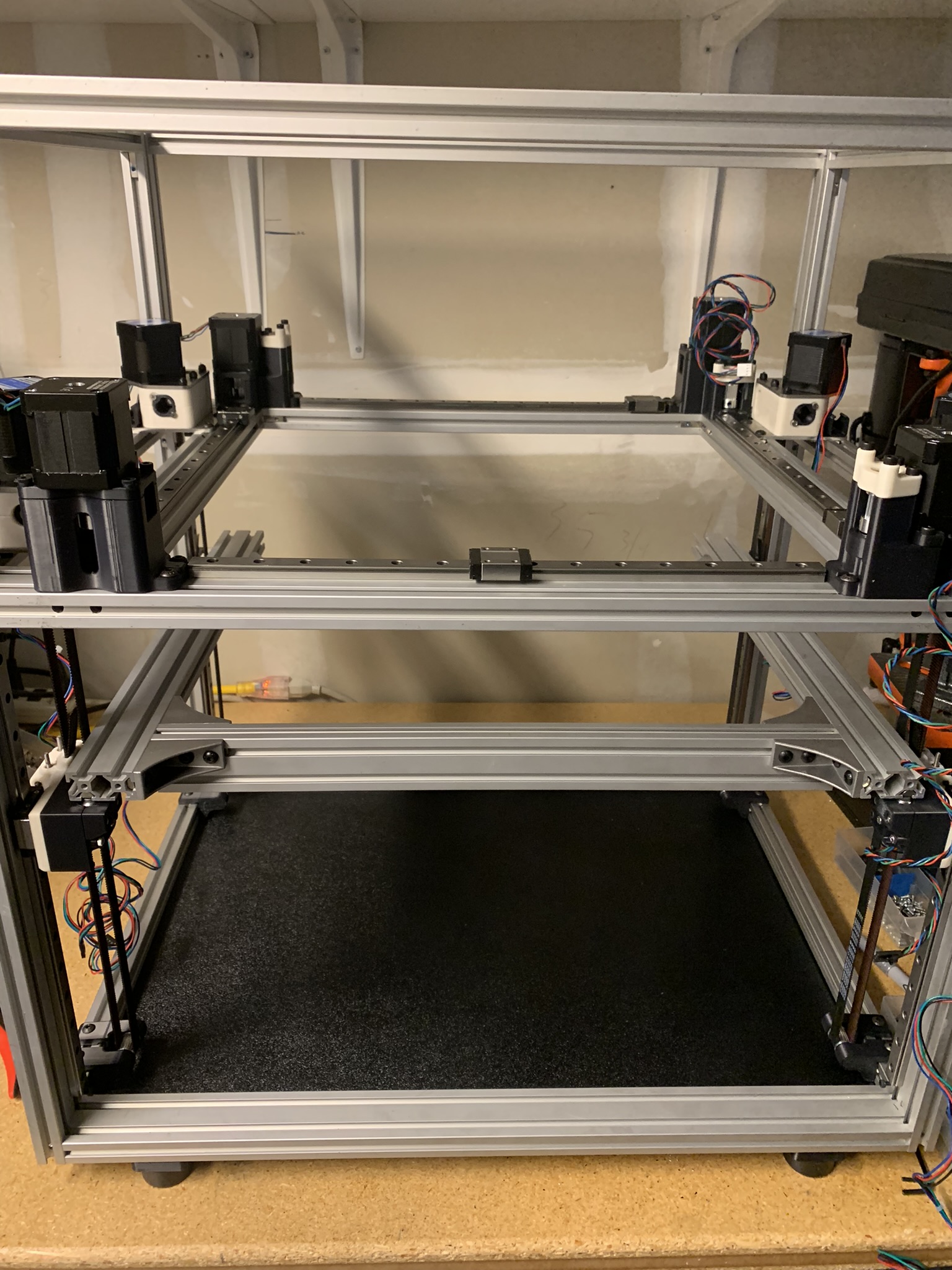
Figure 23: Finished installation of static gantry rails