The gantry has four tensioners: two on the stationary X rails and two on the Y. The X tensioners are identical (not mirror images) to each other and the Y tensioners are identical to each other. Printed parts are identical for all four tensioners.
X tensioners and Y cross
BOM
For each tensioner, you’ll need the following:
- Printed parts
- 2x Long M3 heatset inserts (not pictured)
- 2x Short M3 heatset inserts (not pictured)
- 2x M3x10 SHCS
- 2x M3x16 SHCS
- 2x M3x40 SHCS
- 4x M3x50 SHCS
- 4x M3 Washers
- 2x M3 Square nuts
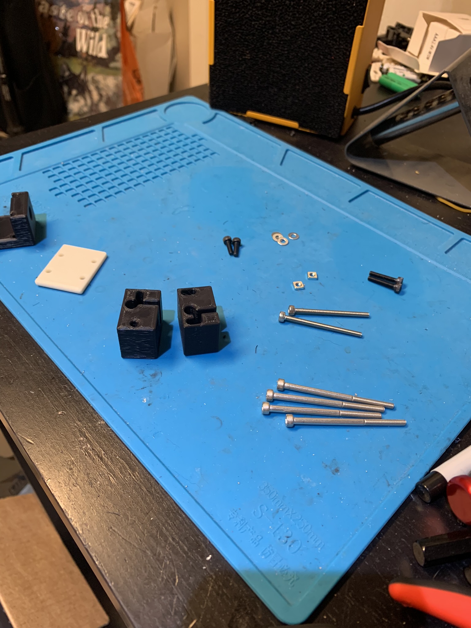
Figure 1: BOM for each tensioner in the gantry
Heatset inserts
Each tensioner has two heatsets at their bottom and two on their right side when looking at the printer from the outside in. The right side takes the long M3 inserts and the bottom takes the short ones. You’ll be able to figure out which side is which by looking at the printed parts and then looking at the eDrawing, the holes that take heatset inserts are larger. Here are some pictures to help:
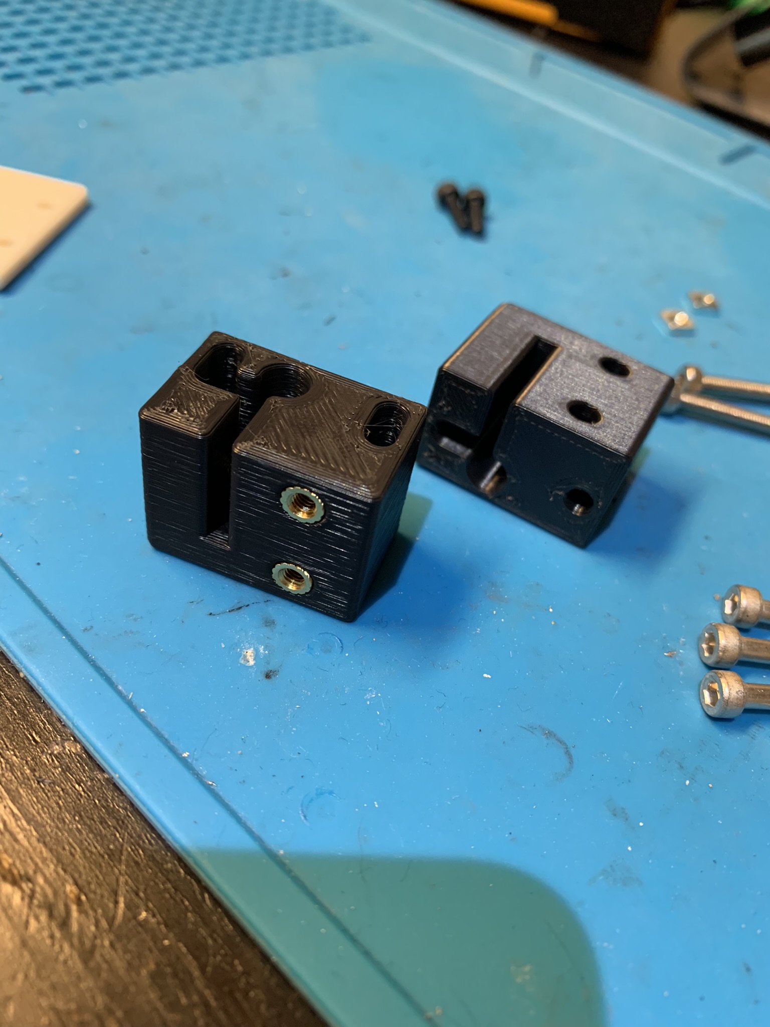
Figure 2: Heatset inserts inside each tensioner in the gantry, one angle
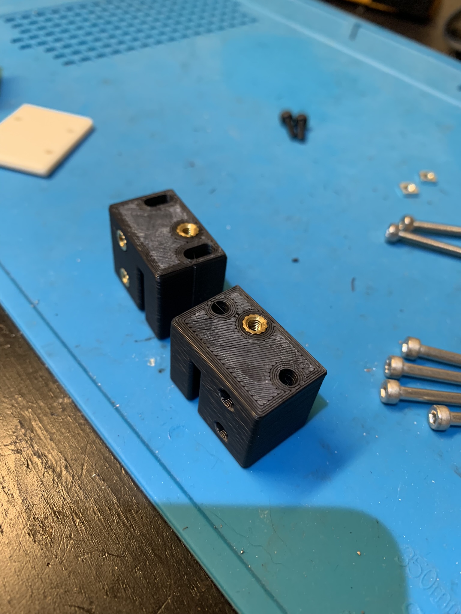
Figure 3: Heatset inserts inside each tensioner in the gantry, another angle
Cross extrusion and rail
Next, we’ll put the rail on the extrusion that will connect the two X tensioners, aka the Y cross extrusion/rail. Lay your rail next to the 1515 extrusion, with the extrusion rotated so that the notches are vertical. Insert M3 square nuts into the top slot of the extrusion, one at both extremes and then alternating rail holes for the rest.
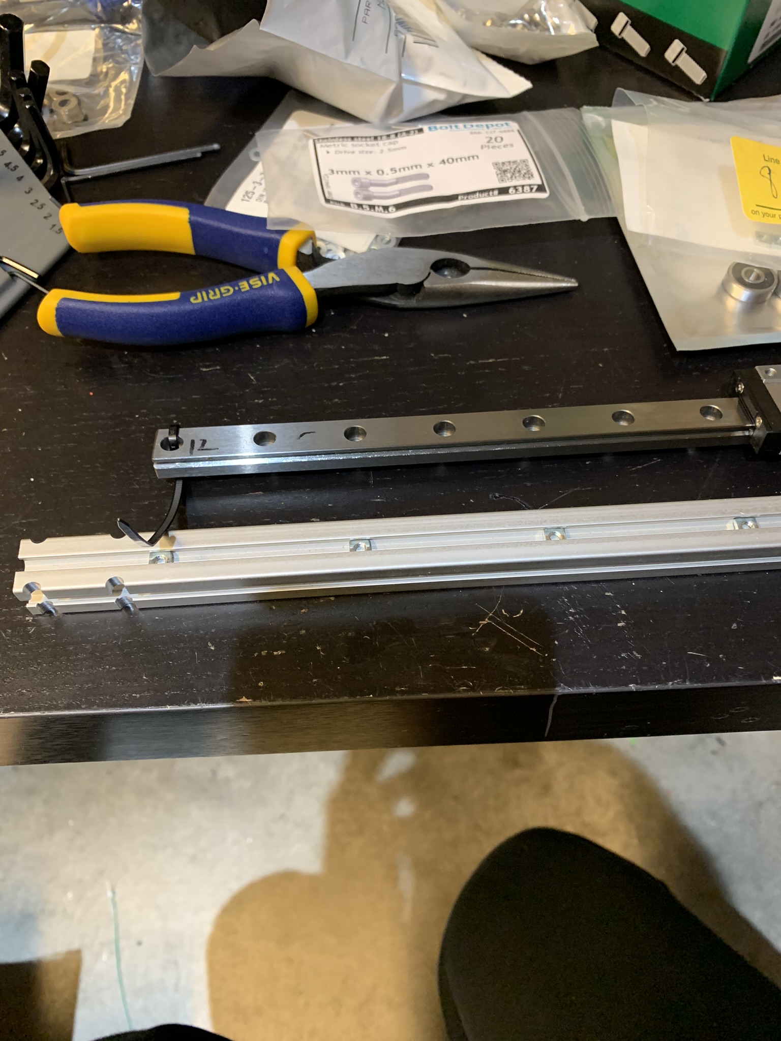
Figure 4: M3 nuts inside the gantry cross extrusion
Put the rail on top and secure it loosely to the extrusion using M3x8 SHCS. I used two M3x16 for the ends and tightened them to prevent the rail from sliding off the extrusion and the carriage from sliding off the rail. I’ll switch those two out for M3x8 after the extrusion is installed in the printer.
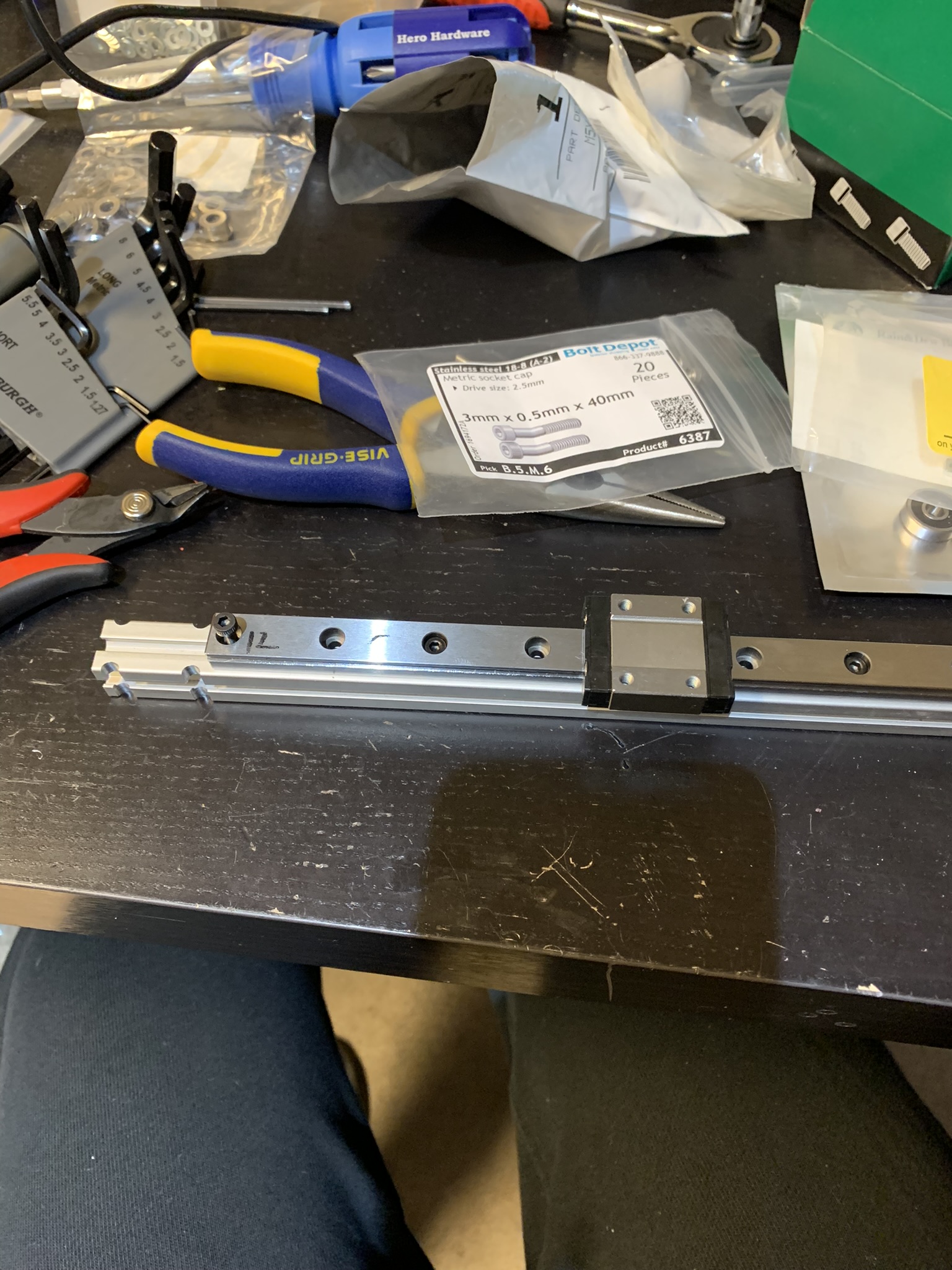
Figure 5: Gantry cross extrusion with rail loosely attached
Insert 2x M3 Square nuts in the side slots at both ends of the extrusion, these are used to bolt the joint to the extrusion.
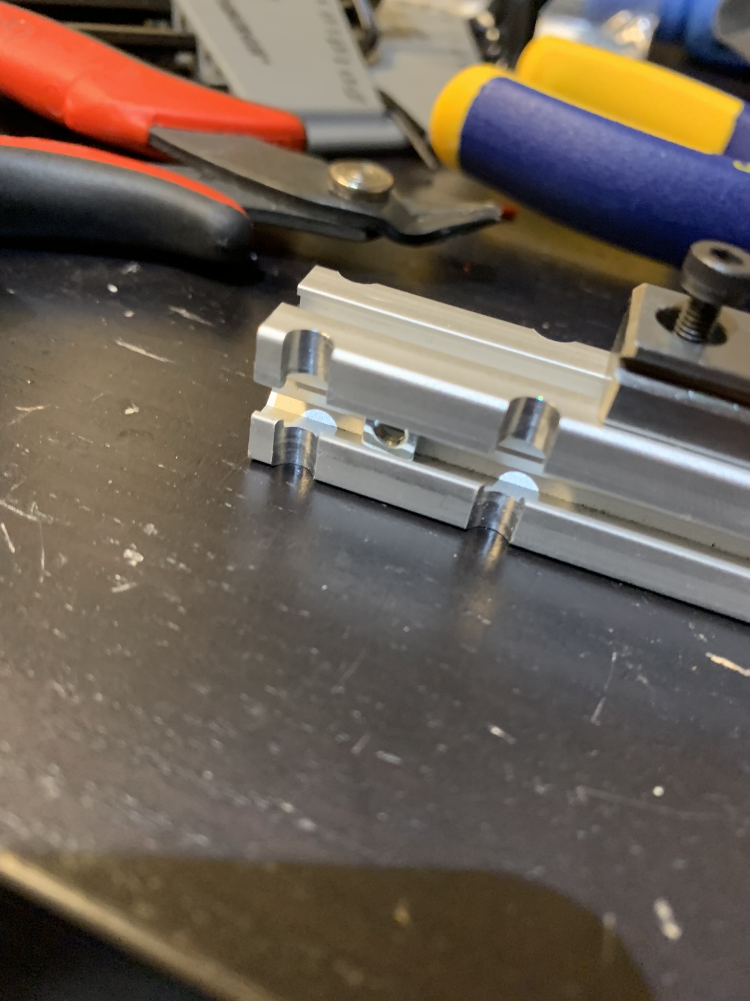
Figure 6: Gantry cross extrusion with side square nuts inserted
Place the printed part on top of each end of the extrusion. Insert 4x M3x50 SHCS into the four holes in each printed part and slide the extrusion back and forth until they go all the way through. Screw M3x10 SHCS through the holes into the square nuts we just placed, make them snug but not tight
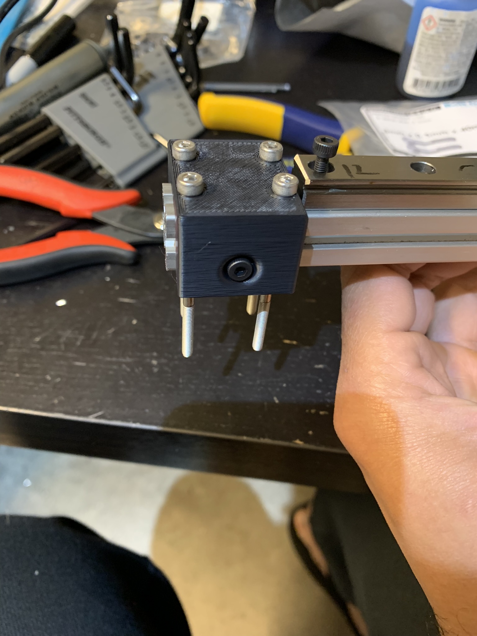
Figure 7: Gantry cross extrusion, printed joint part aligned using long bolts
Installing the belt
Let’s start with the front of the printer. Feed one end of your belt into the left side of the idler pulley on the right.
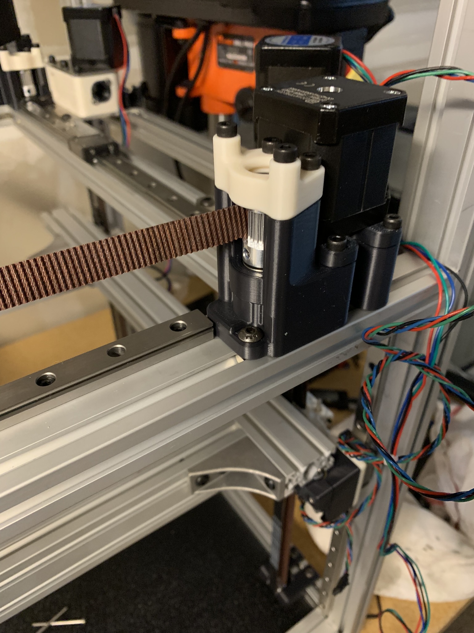
Figure 8: Belt inserted into idler
Push it in till it wraps around the pulley and comes out the right side. You might have to use a hex driver or rotate the idler manually to help it.
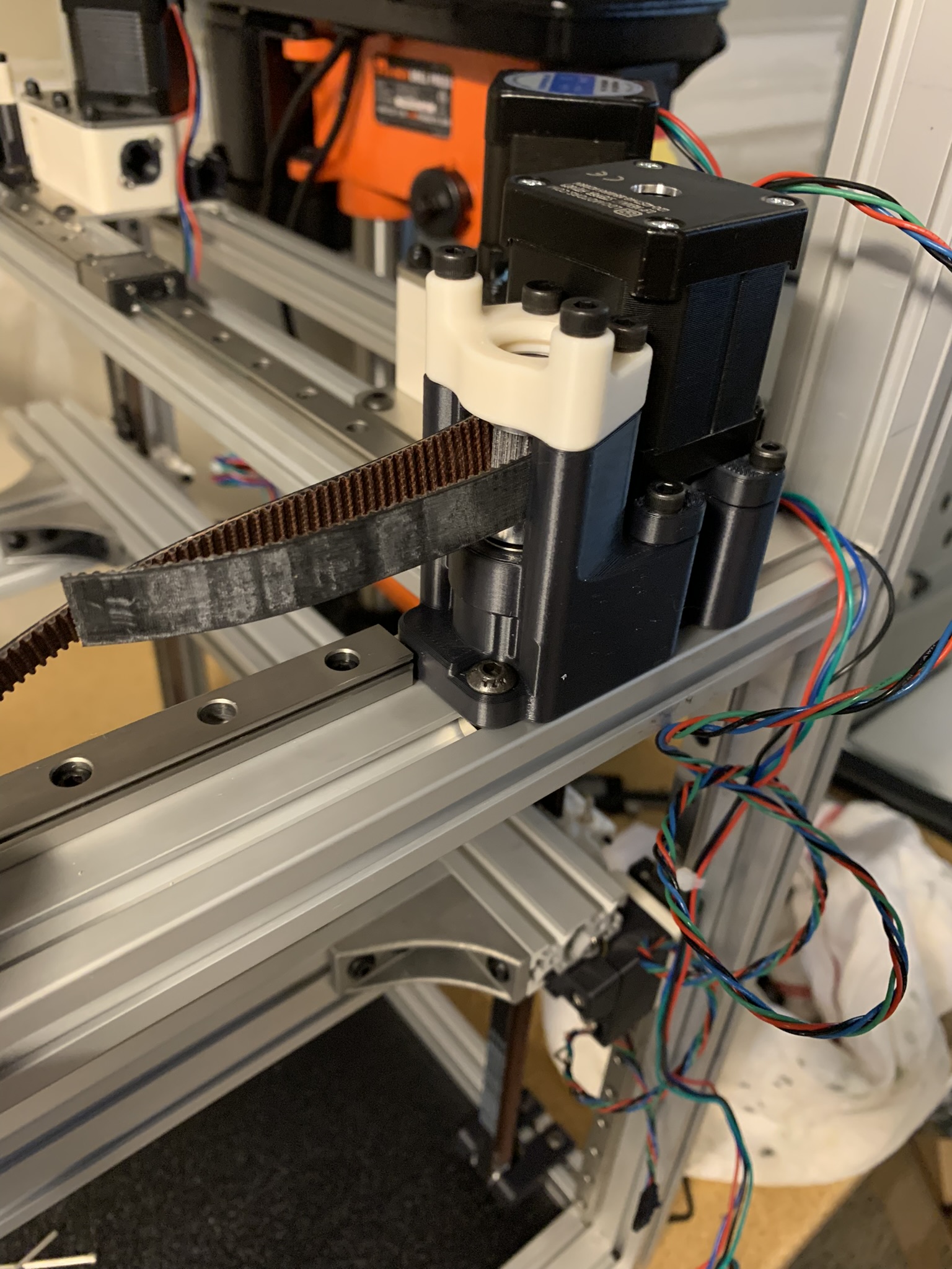
Figure 9: Belt exiting idler
Next, insert it into the left side of the motor pulley on the left. Again, push/help it through and out the right side of the motor pulley.
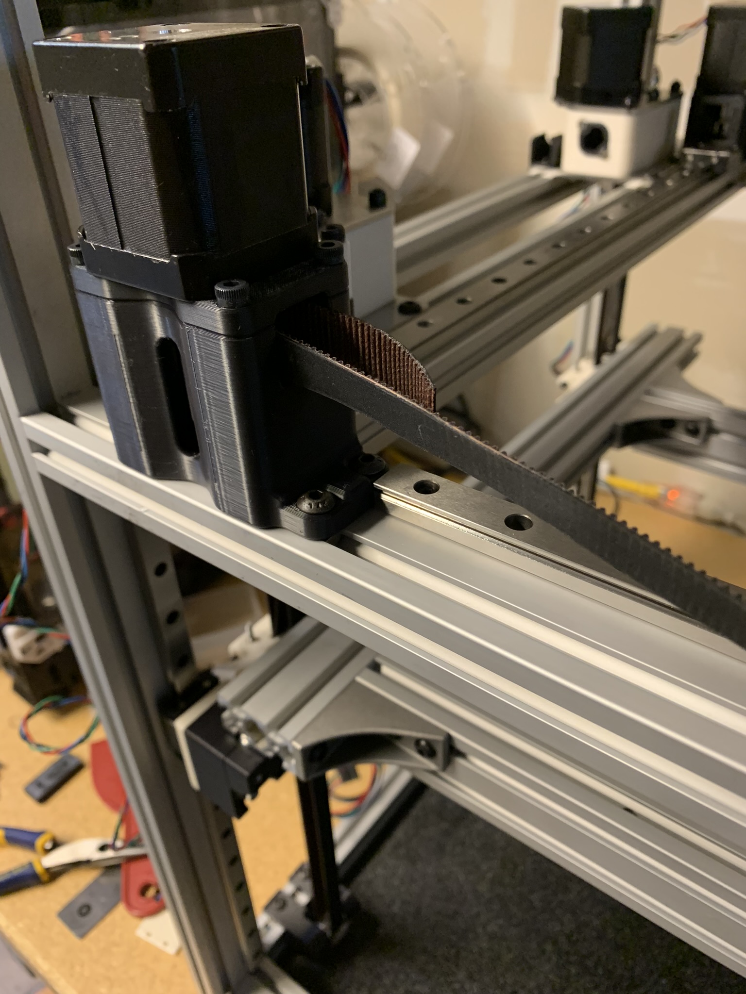
Figure 10: Belt entering and exiting motor assembly
Next, we need to install the belt tensioners. They work identical to how the Z tensioners work, so I won’t go into much detail here.
Each tensioner has two parts: a static one and a dynamic one. The static one - as the name suggests - stays static whereas the dynamic one can be moved to adjust belt tension. The static part has holes on the top and bottom while the dynamic one has slots. Take a close look at both halves and you’ll see what I mean.
Make a loop at the loose end of your 12mm belt and insert it into the static (left) half:
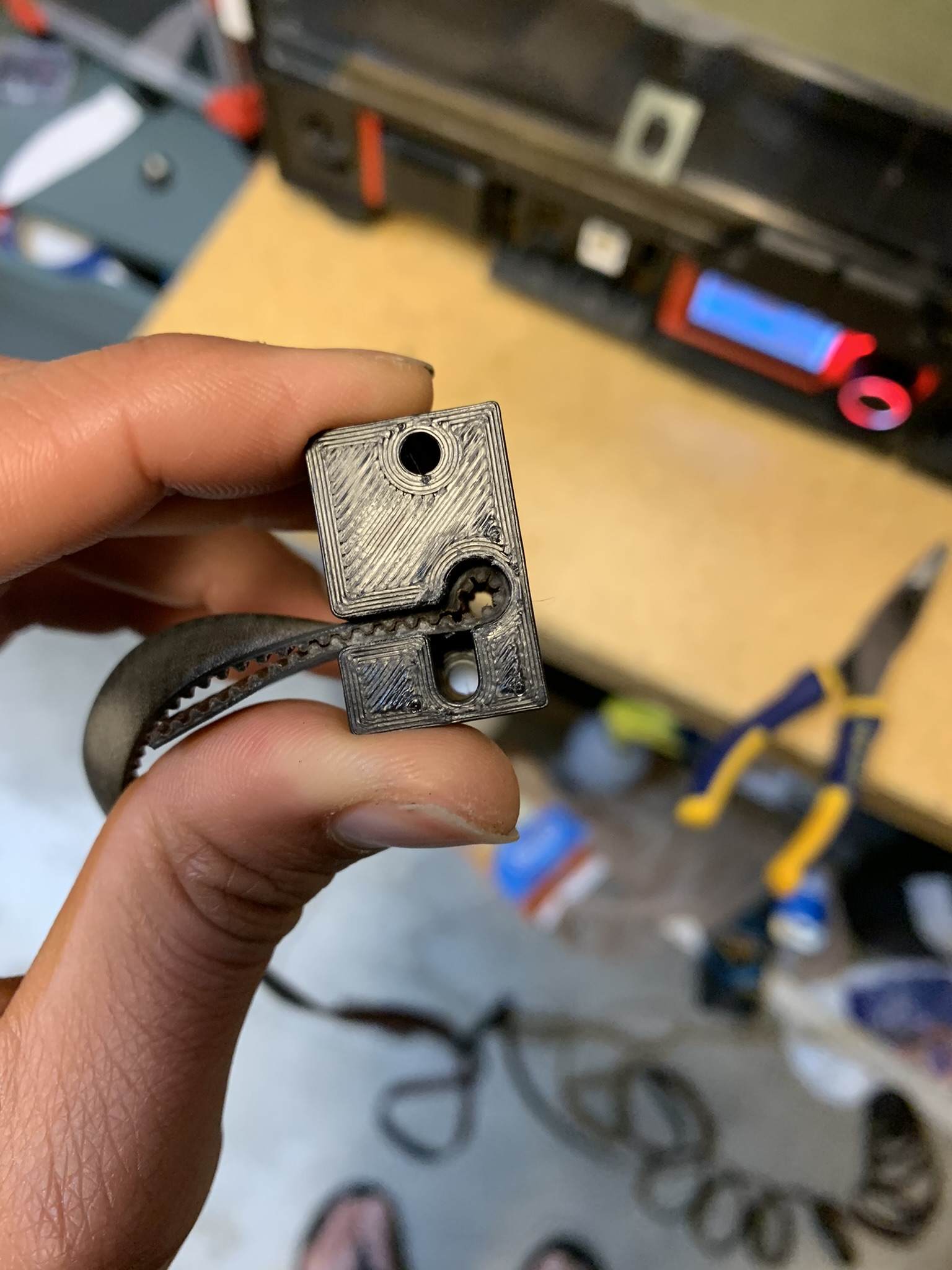
Figure 11: Belt loop inside static tensioner part
Insert a hex driver into the loop and move it around to make some space. Then insert an M3x16 SHCS into the loop, push it in with your thumb or another surface, and tighten it. It doesn’t need to be very tight, it simply exists to stop the belt loop from sliding up and down.
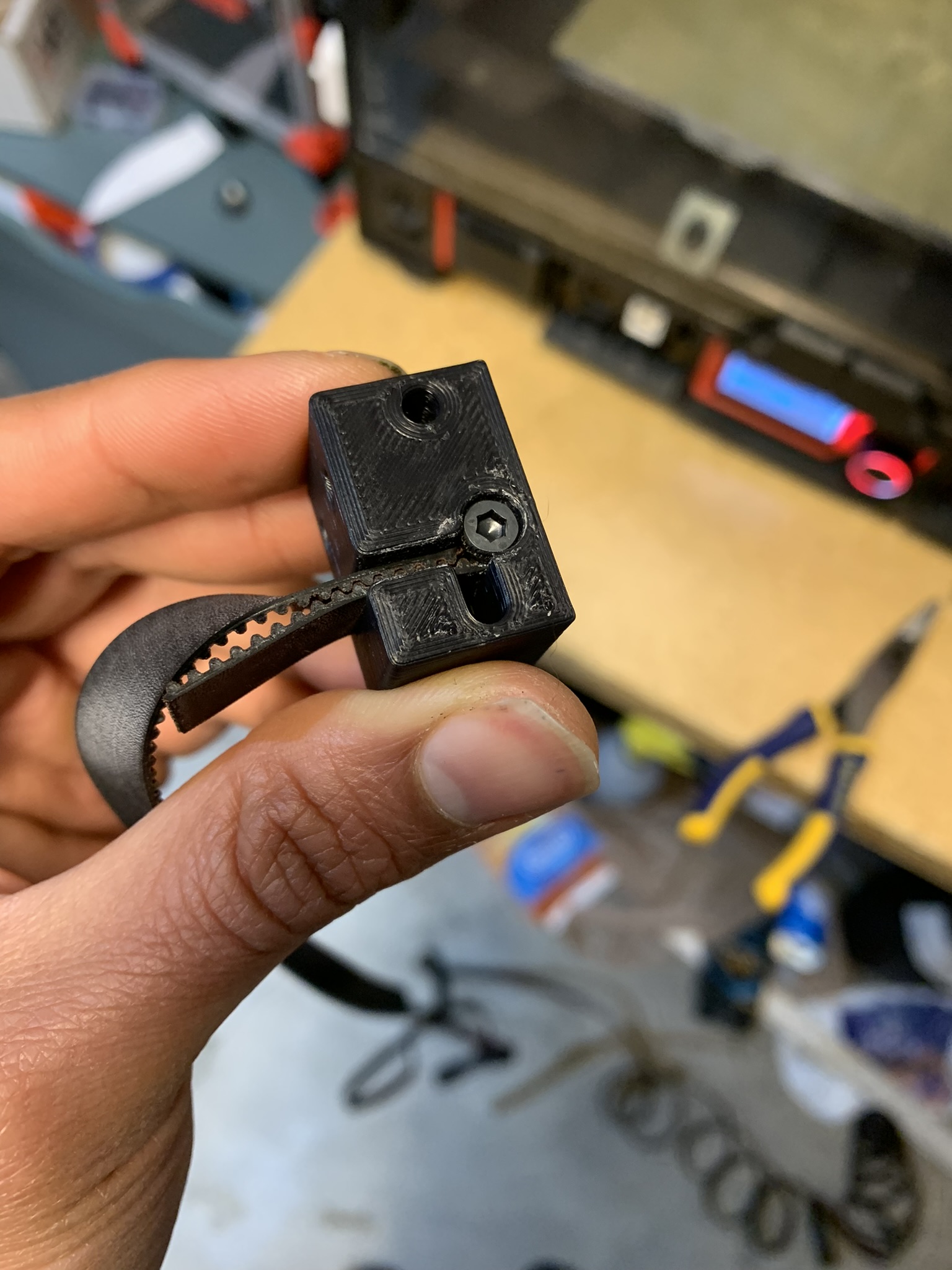
Figure 12: Bolt inside the belt loop inside static tensioner part
Lay your cross extrusion across the X rails, with the cross rail on top. Attach the left half of the tensioner to the X joint with 2x M3x50 SHCS, keep them loose:
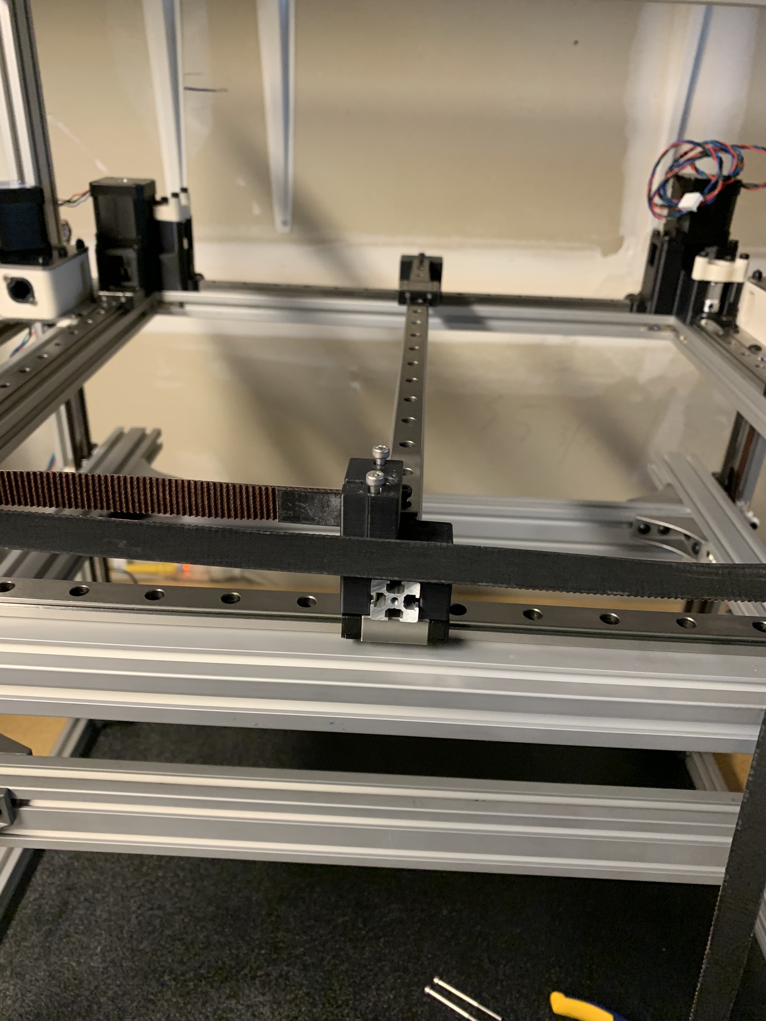
Figure 13: Left half of tensioner loosely attached to X joint
Make a loop at the other end of your belt and insert it into the dynamic (right) half of the tensioner.
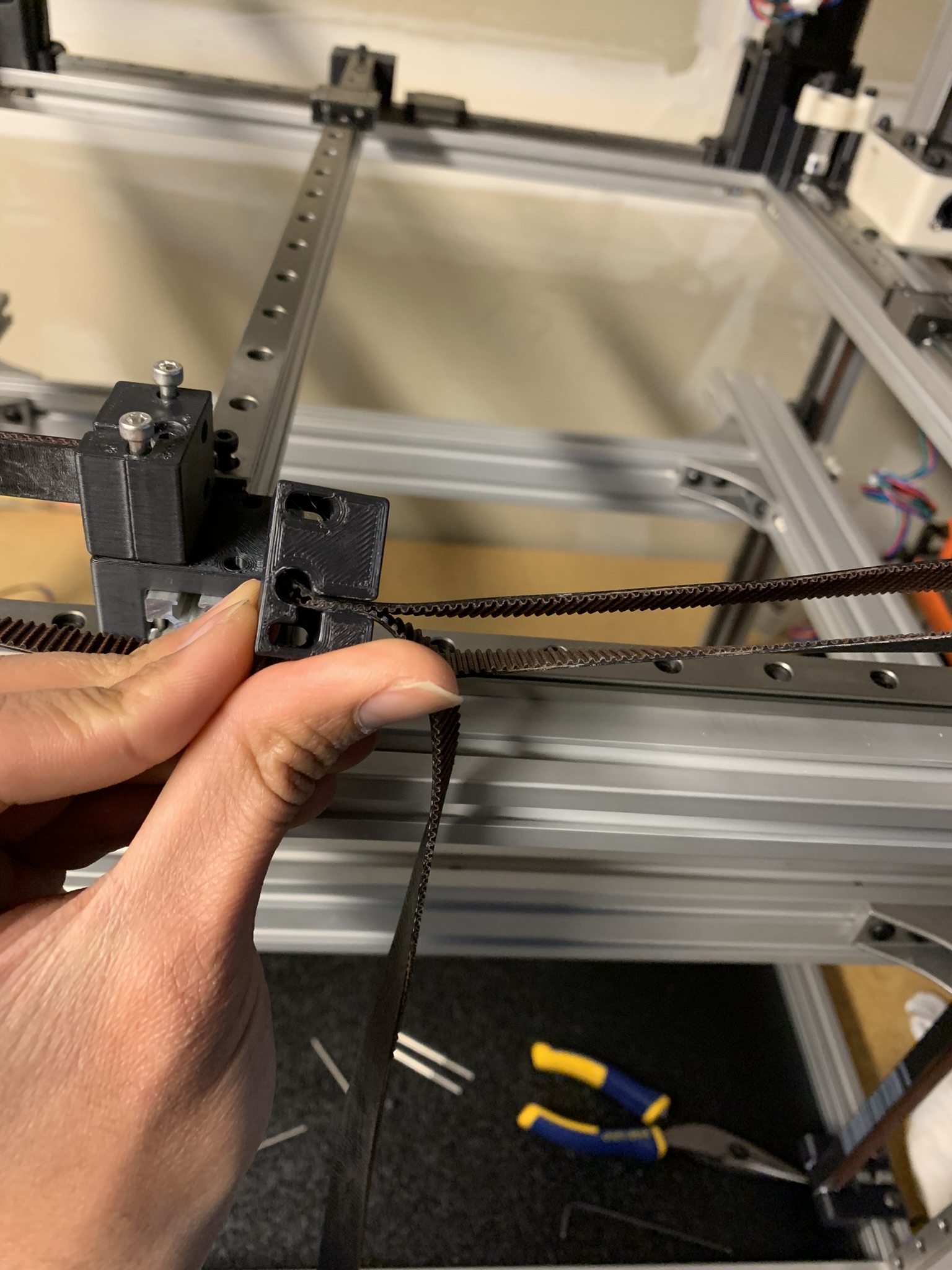
Figure 14: Belt loop inside dynamic tensioner part
Make room inside the belt loop with a hex driver and secure it with an M3x16 SHCS:
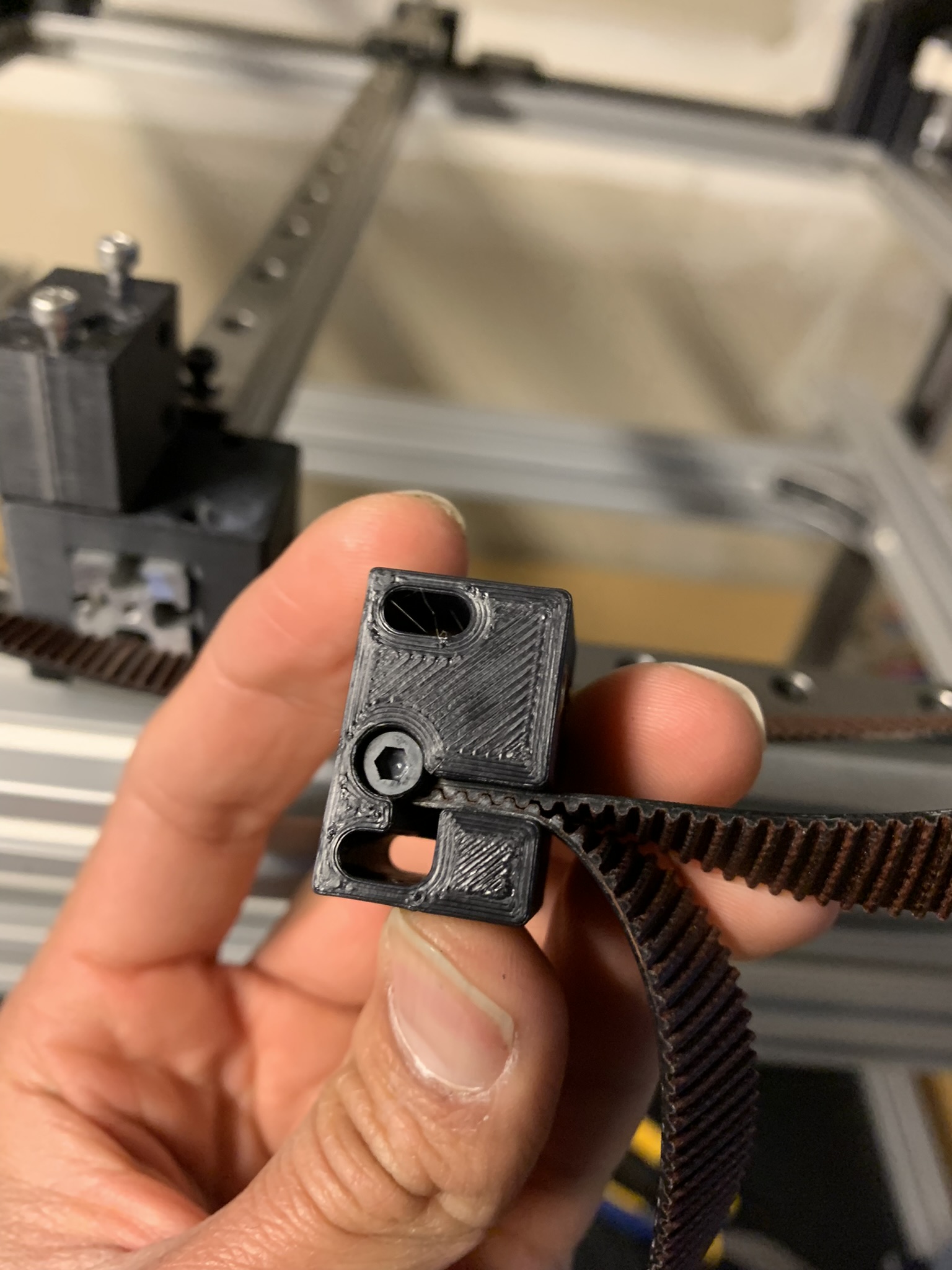
Figure 15: Bolt inside the belt loop inside dynamic tensioner part
Figure out how long your want your belt to be. The belt length will be similar to what you did for the Z belts: with light tension on the belt, there should be 6mm distance between the two tensioner halves.
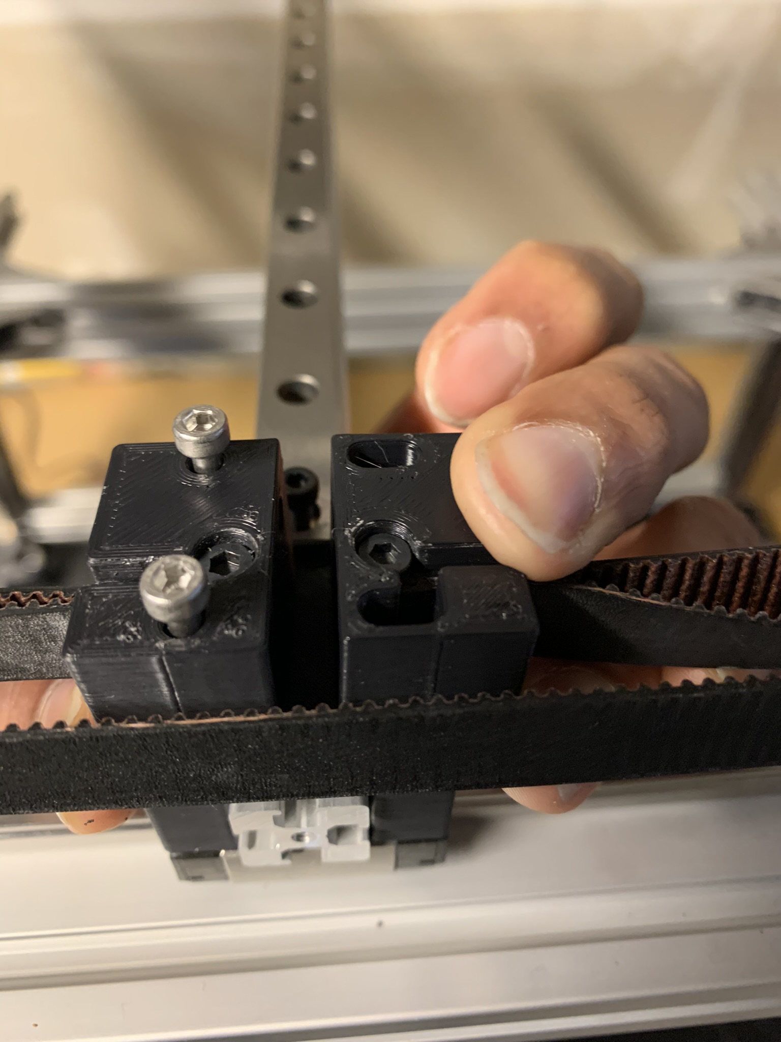
Figure 16: Rough distance between the two tensioner halves
Cut the belt at the desired length, take the belt out and cut three more segments of the exact same length, down to the tooth count. Reinstall the belt.
Bring the right half close to the left half and loosely attach the two using 2x M3x40 SHCS.
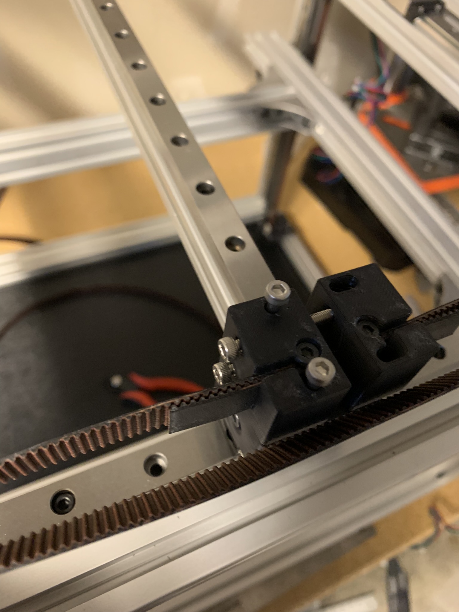
Figure 17: Tensioner halves loosely attached
Tighten both bolts to bring the tensioner halves towards each other. Stop when you’re satisfied with the belt tension. I recommend gently plucking the outside aka the long side of the belt with your finger, and using an audio frequency app on your phone to measure belt tension. You want the belt’s frequency to be roughly 60-65 Hz. If you’re unsatisfied even when both halves are flush, you’ll have to tighten the belt further by adjusting the meshing of the belt inside the right half of the tensioner and trying again.
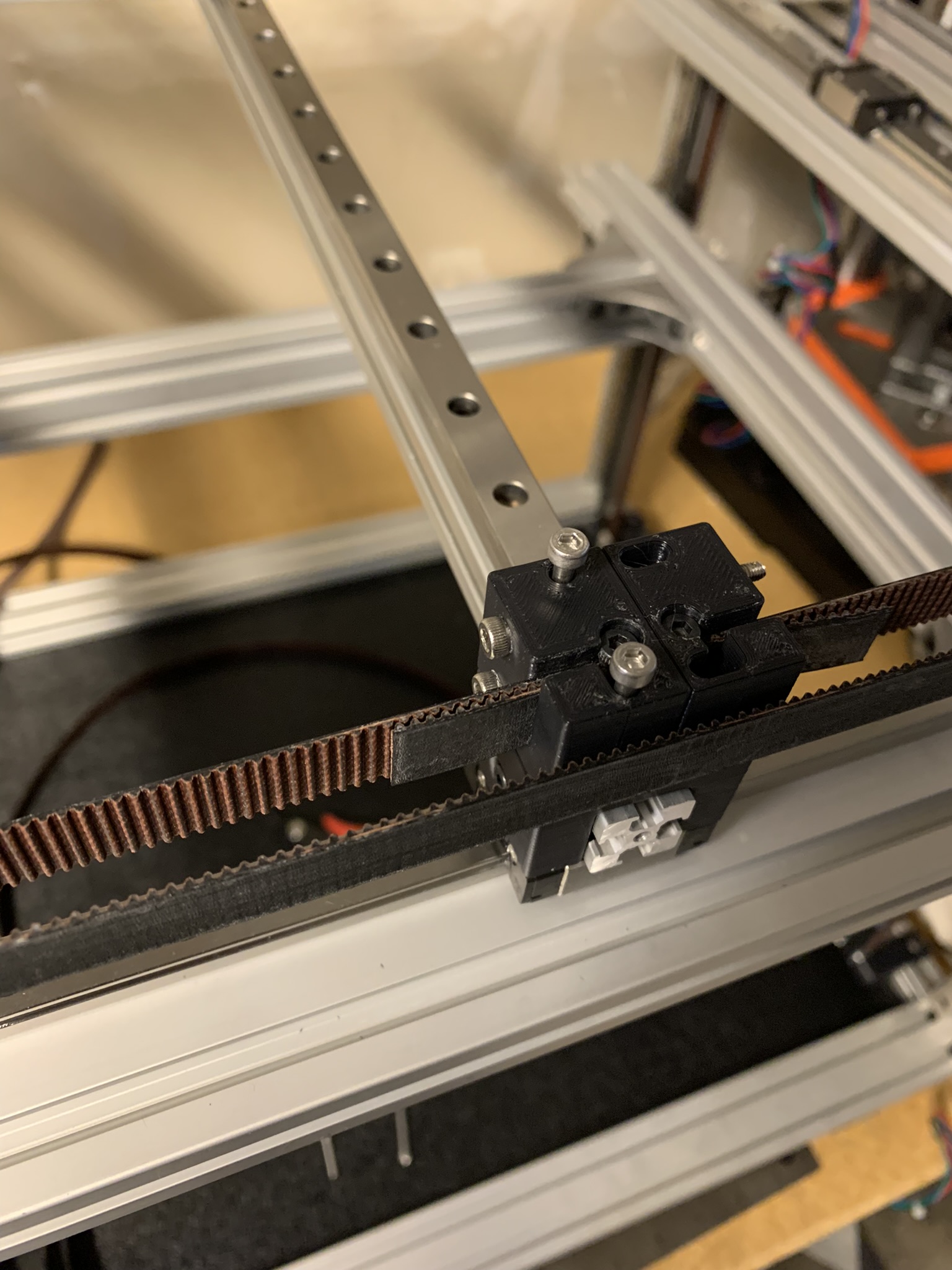
Figure 18: Tensioner halves tightly attached
Now, loosen the two horizontal bolts joining the tensioner halves, and take out the two vertical bolts securing the left half of the tensioner to the joint. Place the printed accent part on top and re-tension the tensioner. Use the 4x M3x50 SHCS with 4x M3 washers to secure everything once again. Leave the bolts snug but not tight.
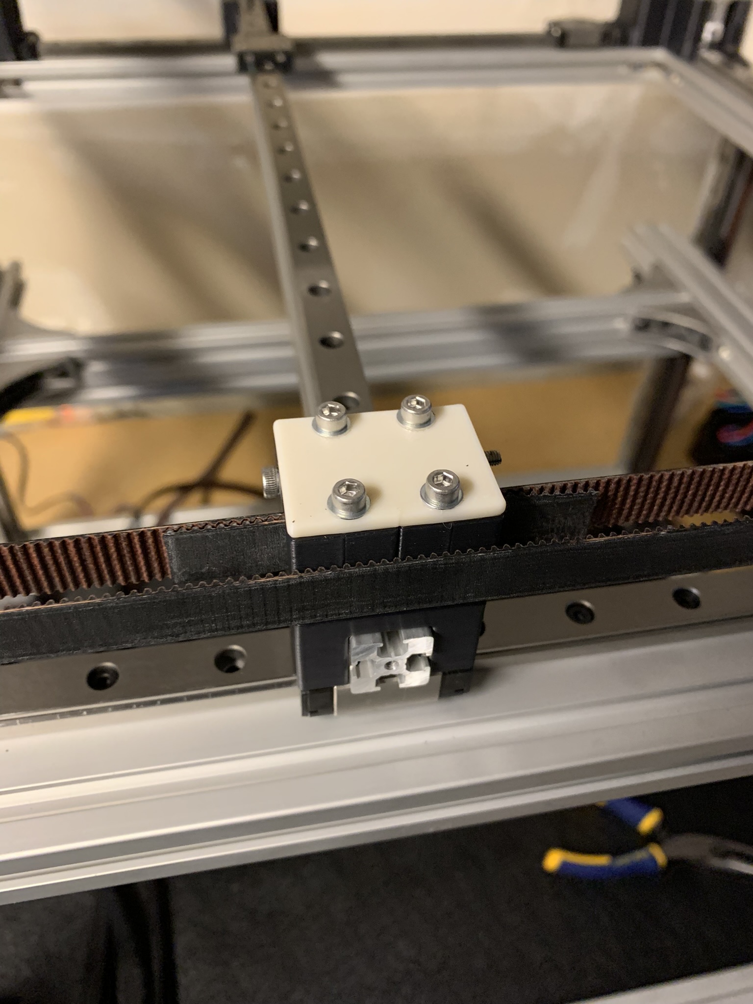
Figure 19: X tensioner assembled
Now, it’s time to check range of motion. Move your cross rail to the extreme right and see if the X carriage reaches the end of the rail. You might find that your excess belt gets in the way:
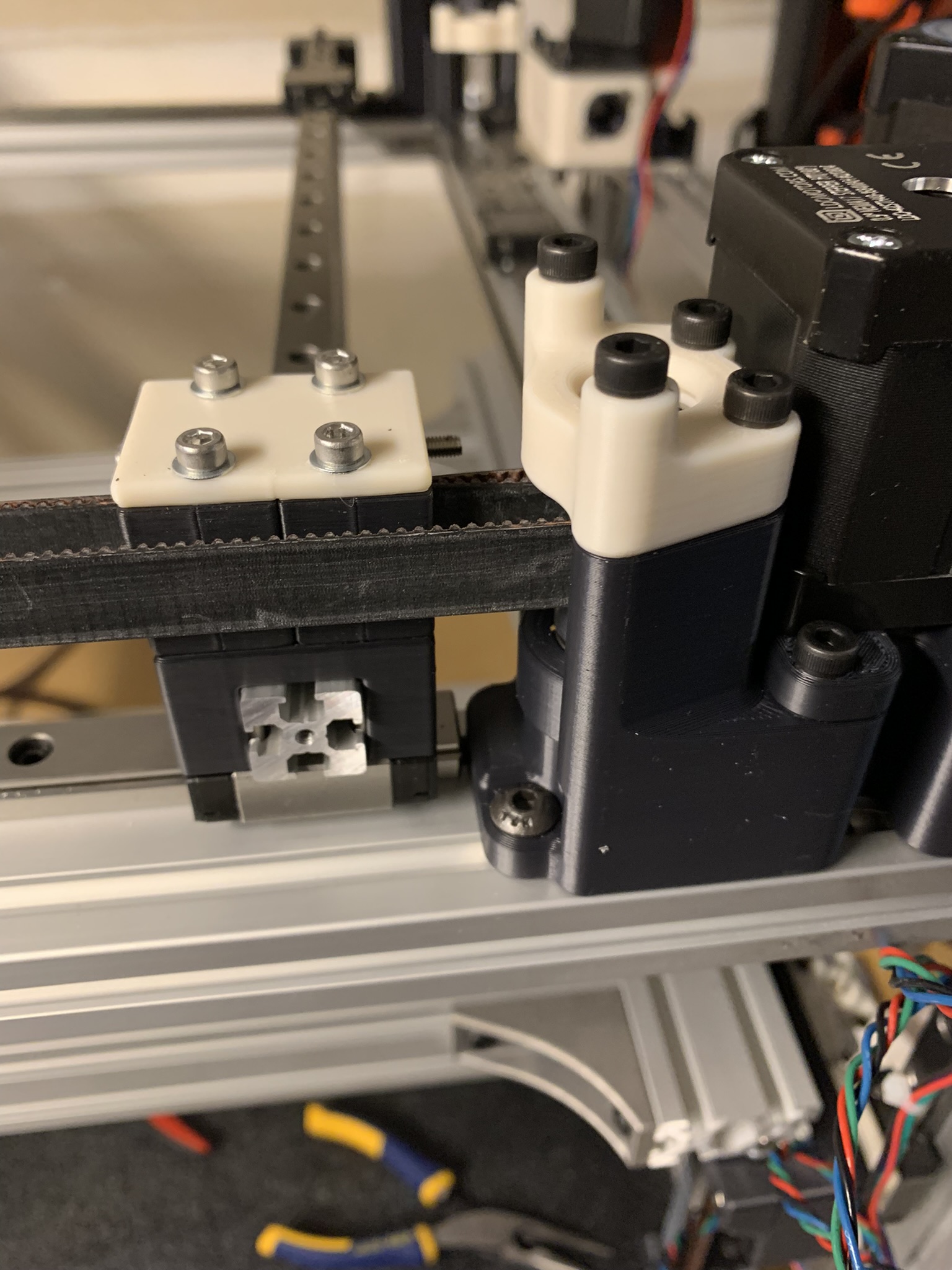
Figure 20: X joint cannot reach X max
Shorten the belt 1-2 teeth at a time till your carriage hits the end of the rail.
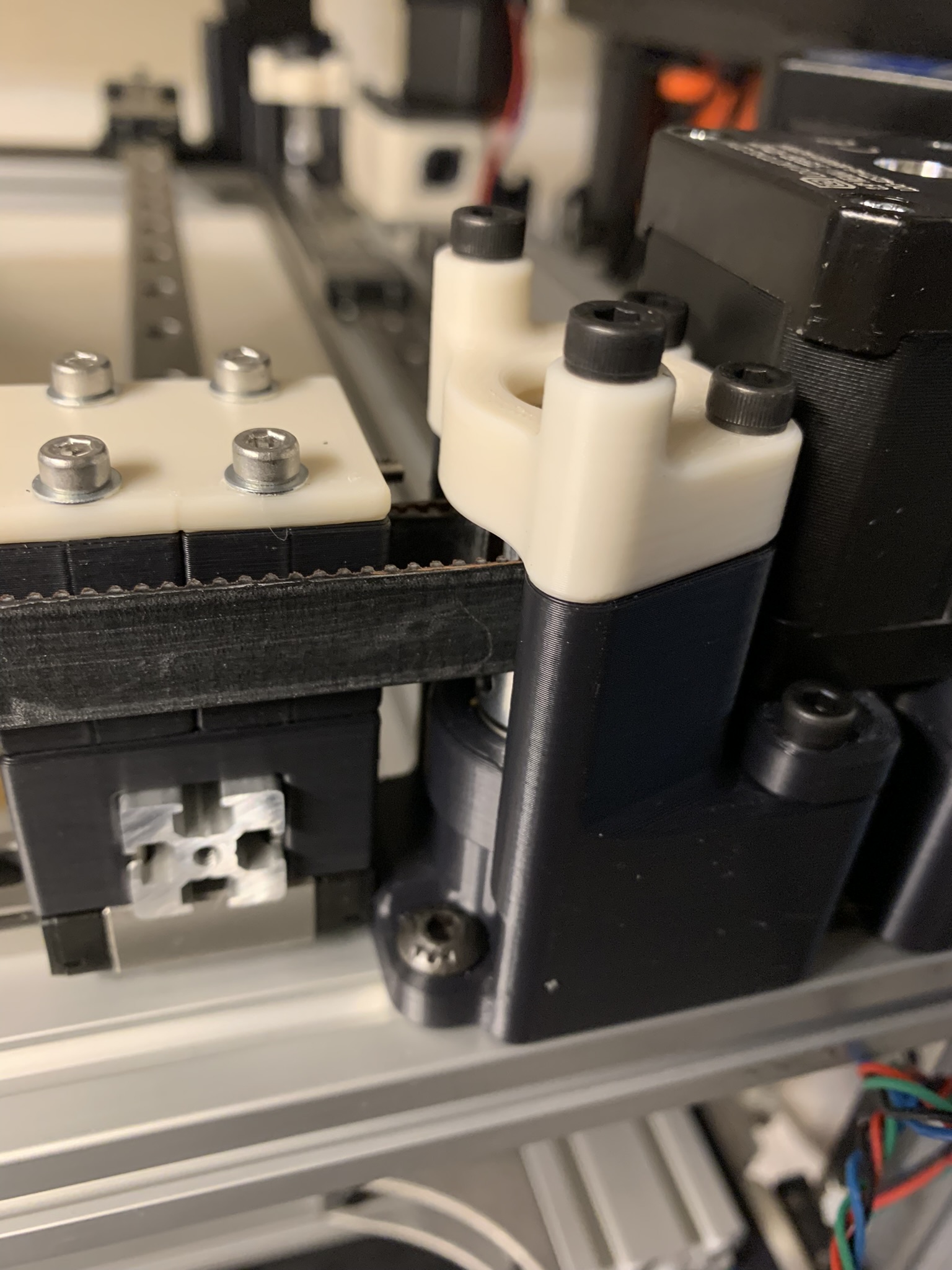
Figure 21: X joint does reach X max
Repeat for all the way left: the carriage should reach the end of the rail. If not, shorten the excess.
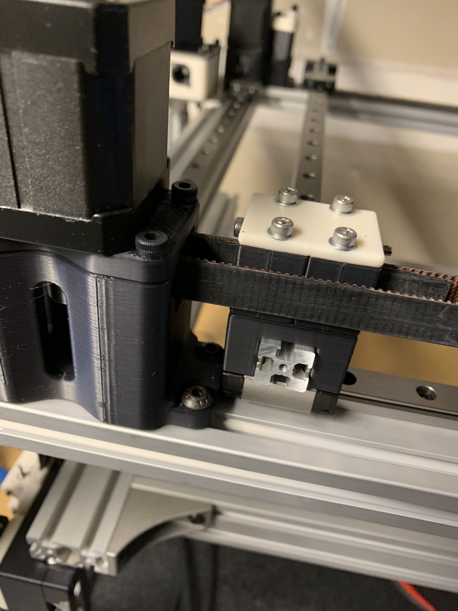
Figure 22: X joint does reach X min
Rotate your printer 180 degrees and repeat this process for the other X tensioner. After that, it’s time to “tram” the cross Y extrusion to X MIN. I don’t know if this is required for the k2, but I did it to derack the gantry on my Voron V2, so I decided to do it here too. Move the Y cross extrusion to X MIN (aka the minimum position for X, this is the right side of the printer if looking at it from the back as in the picture below)
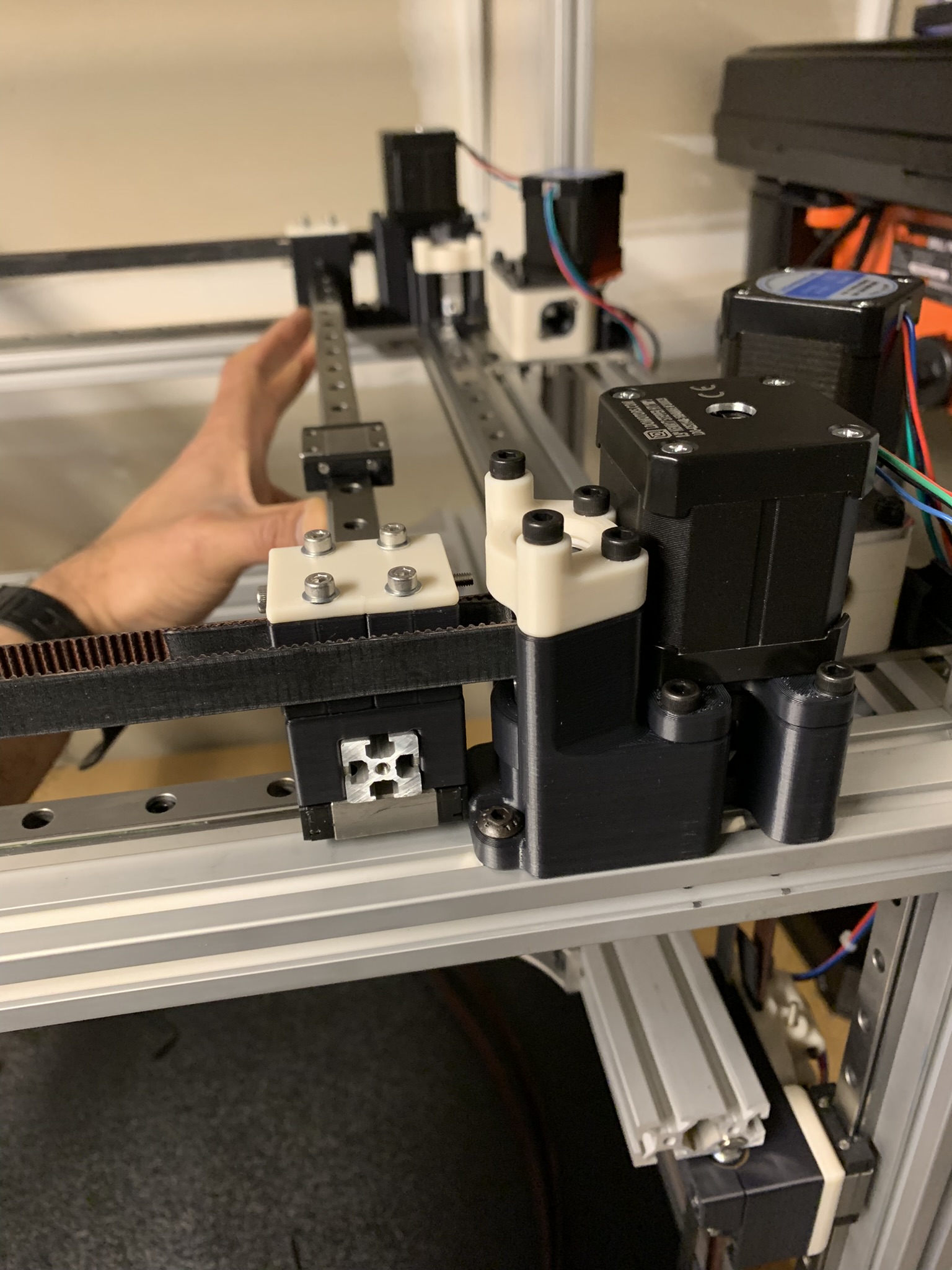
Figure 23: Tramming Y cross extrusion to X min
Make sure the front and back carriages are both at the end of their travel, hold the extrusion there and tighten all 8x M3x50 bolts. Also tighten the 4x M3x10 bolts going into the sides of the joints and into the cross extrusion.
Lastly, we’re going to align and secure the Y rail to the extrusion. Position the rail so that it’s roughly centered on the extrusion. There will be a 1-2 mm gap at each end:
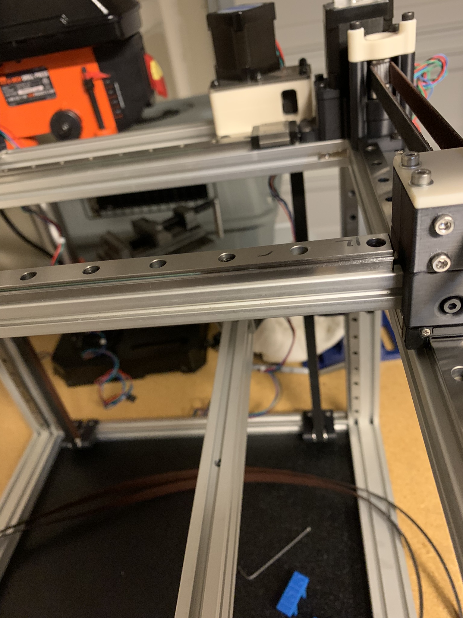
Figure 24: Small gap between Y rail’s end and X tensioner
Use the printed jigs to align the rail and tighten all bolts. If you used M3x16 SHCS at the ends of the rails, remember to switch them out for M3x8 SHCS. I’ve covered the rail alignment procedure in detail before, so I won’t go into it again.
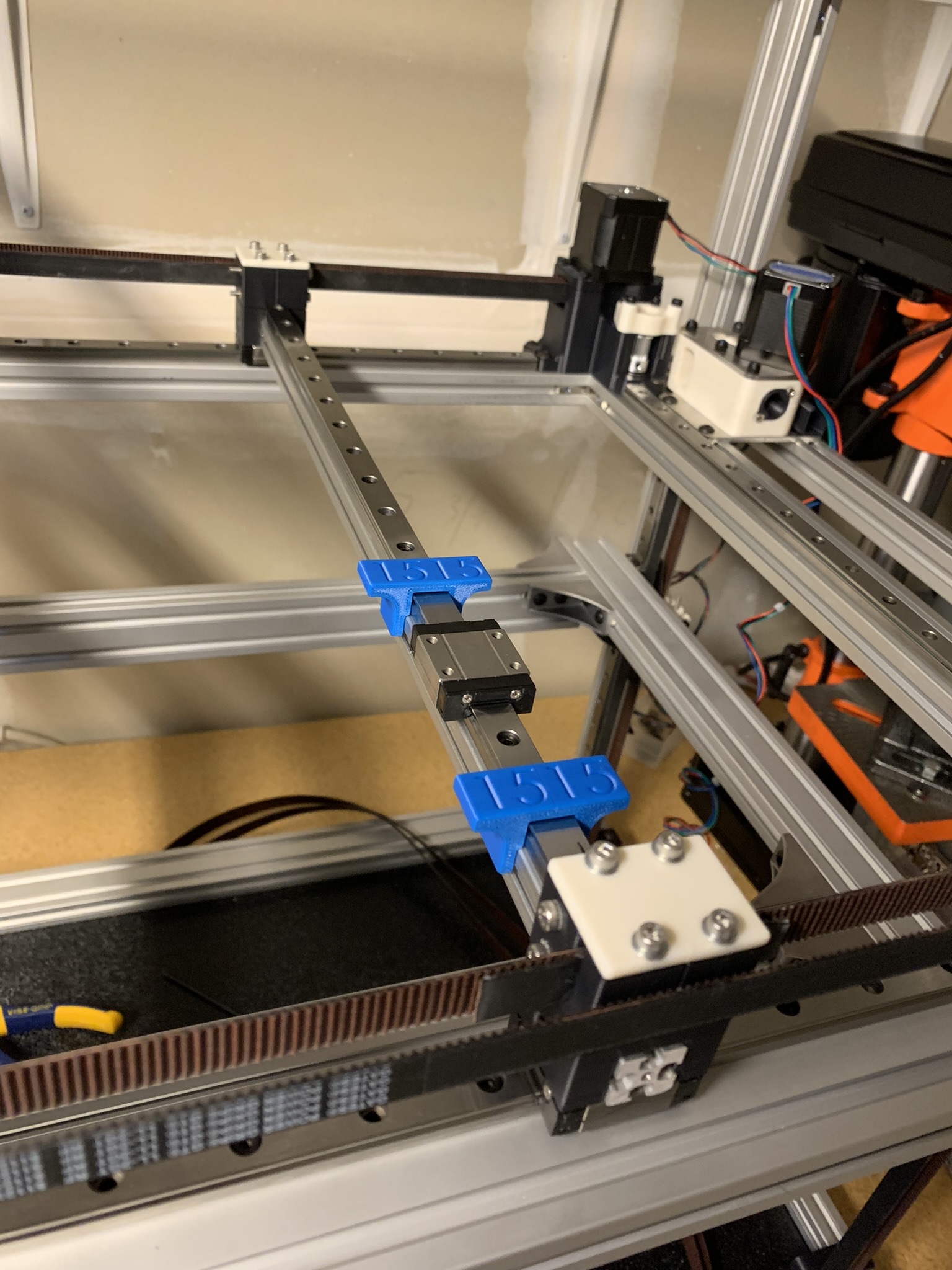
Figure 25: Y rail aligned and secured to the extrusion
Y tensioners and X cross
These are largely identical to the X ones, so I’ll only call out differences.
Cross extrusion and rail
For the X cross extrusion, the extrusion sits on top of the printed joint part. Align it with M3x50 SHCS as before.
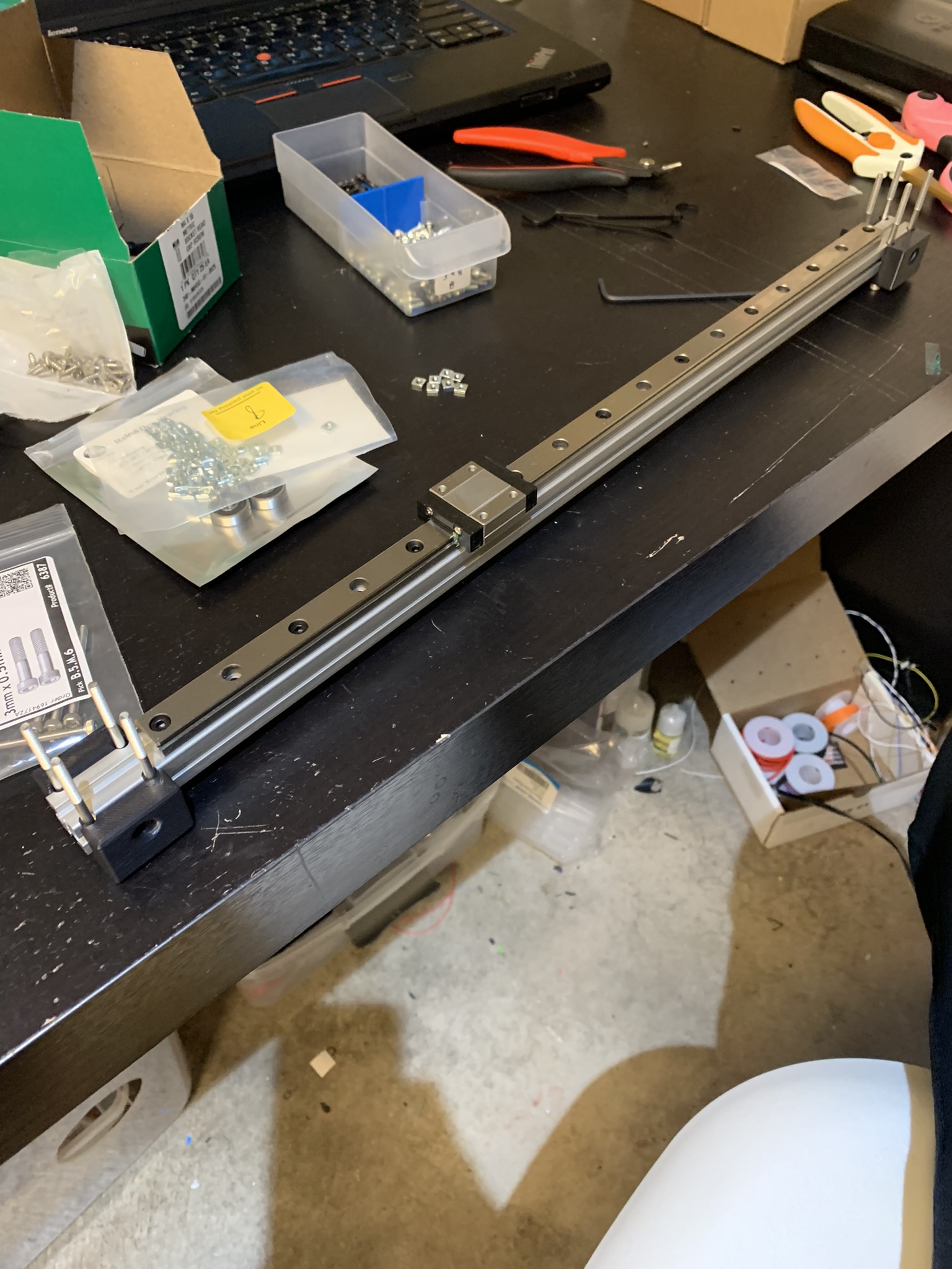
Figure 26: X cross extrusion sitting on top of printed joint, aligned
Install the belts and tighten the tensioners on both sides.
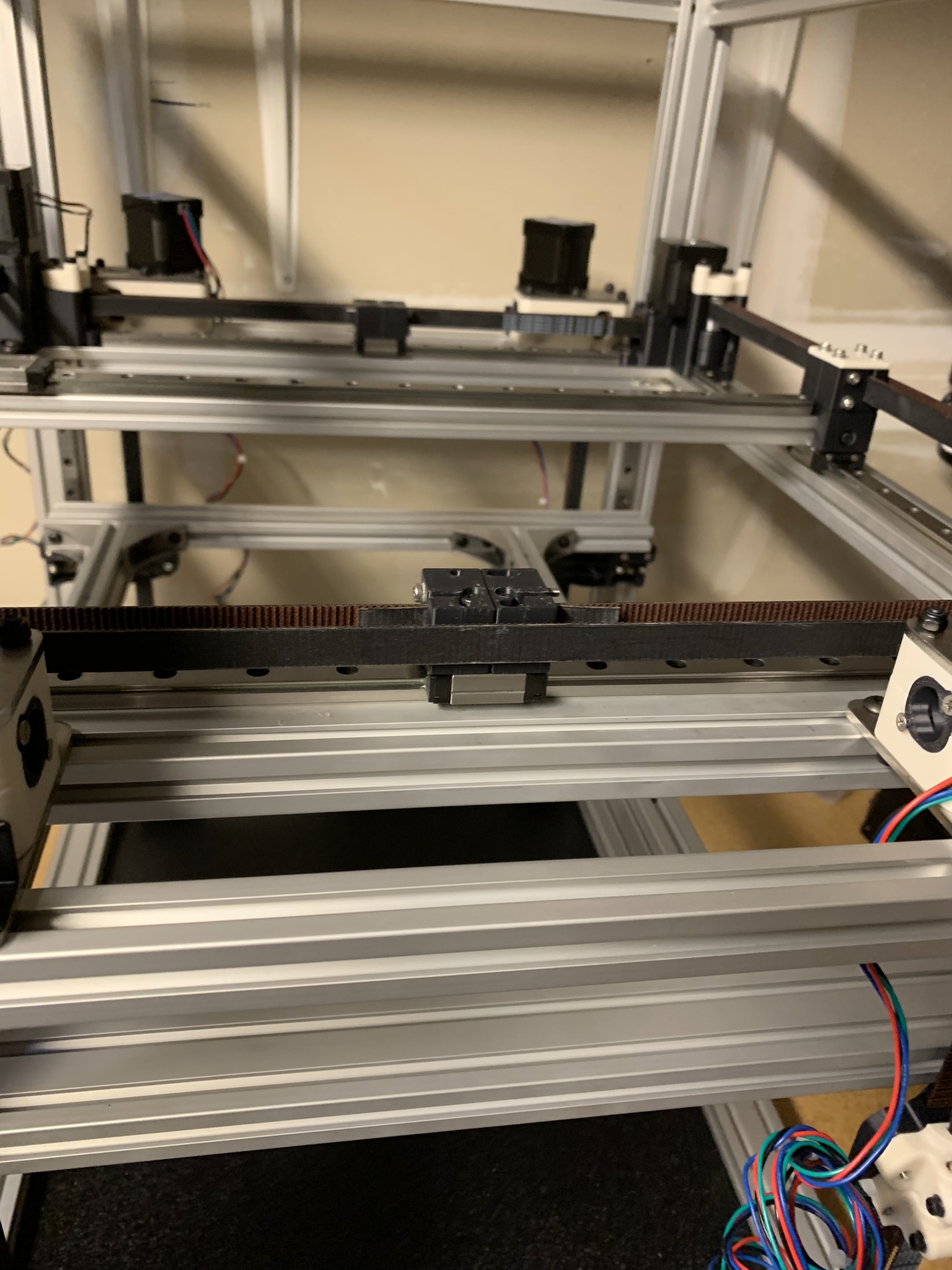
Figure 27: Y belts installed and tensioner
Once that’s done, lay the extrusion on top with the rail facing up. Keep the Y cross rail’s carriage on the left of the X cross extrusion.
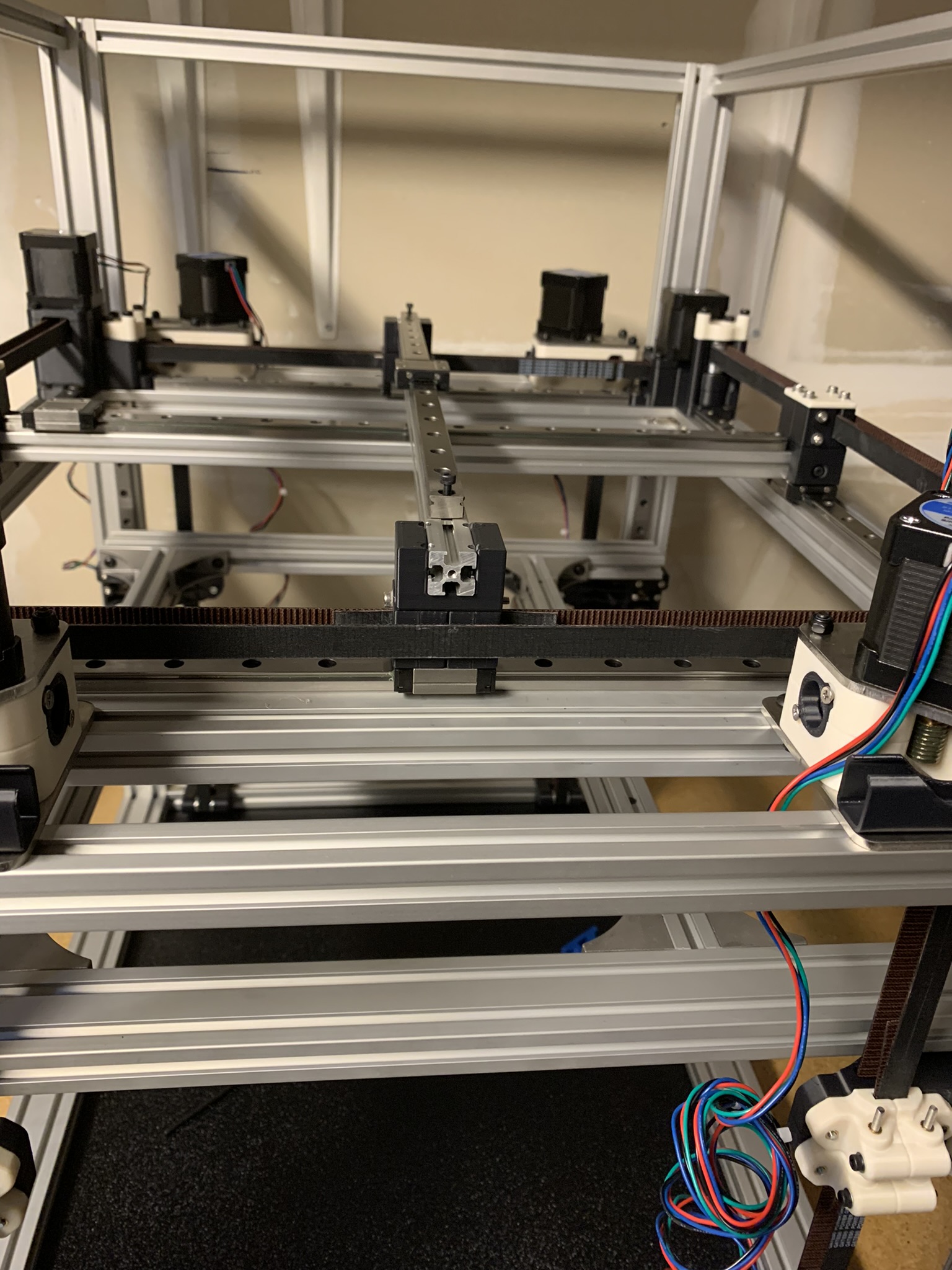
Figure 28: X cross extrusion sitting on top of Y tensioners
Lay the accent piece on top and align the extrusion to the tensioners and joints using 8x M3x50 SHCS with 8x M3 washers.
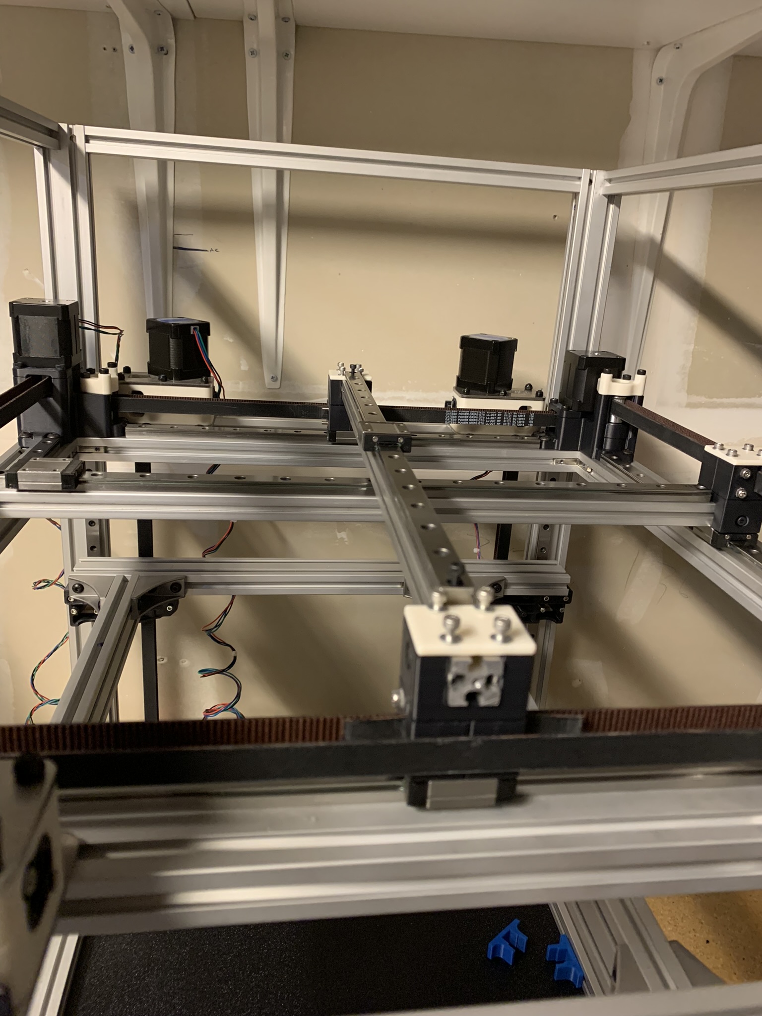
Figure 29: X cross extrusion, aligned
Tighten the bolts till they’re snug but not tight. Adjust belt excess as before till your X cross extrusion has full range of motion on both ends. Tram the X cross extrusion to Y min (left side in the picture below) and tighten all 8x M3x50 SHCS and 4x M3x10 SHCS (the ones in the sides of the cross extrusion).
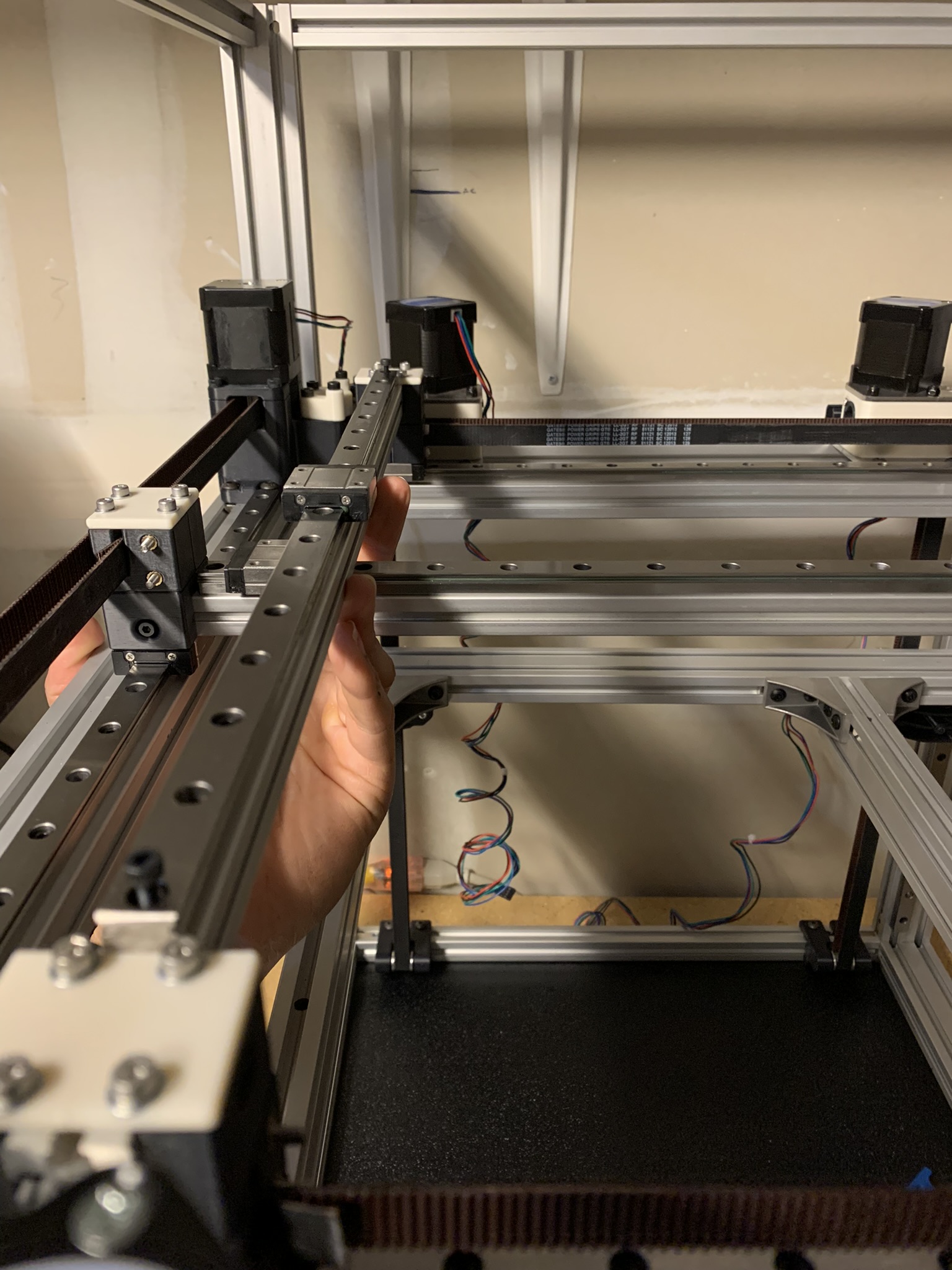
Figure 30: Tramming X cross extrusion to Y min
Align the rail as before and securely attach it to the extrusion.
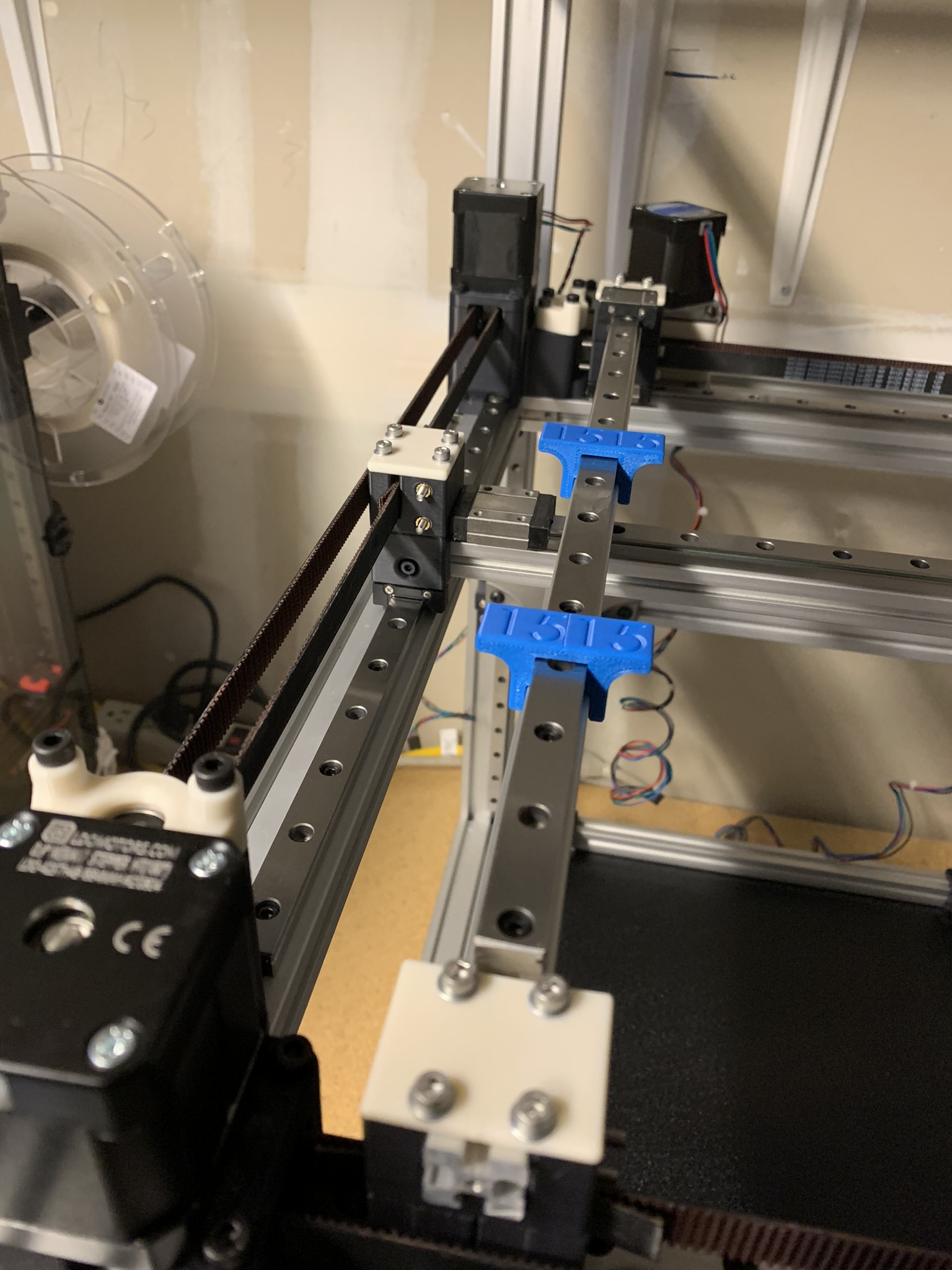
Figure 31: X cross rail securely attached to the extrusion
Loctite
I saved this for the very end because I wanted the gantry to be solidly assembled before worrying about loctite. And it’s easy to apply at this stage. For each tensioner, remove the 4x vertical M3x50 SHCS and 2x horizontal M3x10 SHCS one at a time, apply loctite, and screw them back in.
And we’re done with the cross gantry belts, extrusions and rails.
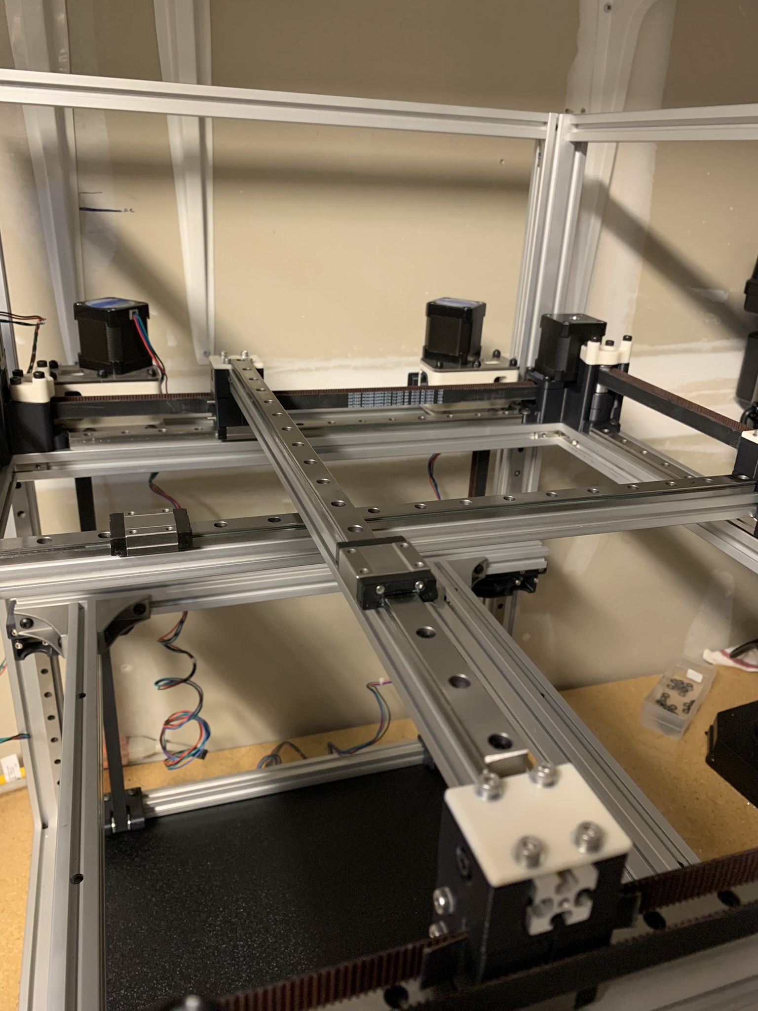
Figure 32: Finished cross gantry belts, extrusions and rails