In this part, we’re going to build and install the frame that the bed sits on. We’re also going to install the bottom plate, feet, tighten the Z tensioners, and bolt them in. Let’s get started.
Building the bed frame
Take a look at the eDrawing and note the orientation of the four extrusions that make up the bed frame. The two extrusions with holes through them sit “vertically” at the back and front, the remaining two sit “horizontally” at the sides. Also note that the external brackets used to hold them together have a long side and a short side: the long side sits along the front and back extrusions.
Starting with the front left, use M5x10 BHCS and roll-in nuts to secure the front extrusion to the left one. Position them so that the external bracket is flush at the front left corner.
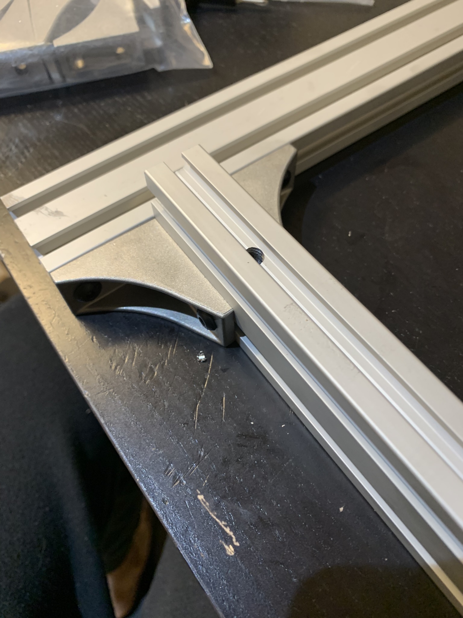
Figure 1: Extrusions attached at front left corner of the bed frame
Position the back extrusion 102mm from the back end of the left extrusion and secure it with bolts and roll-in nuts.
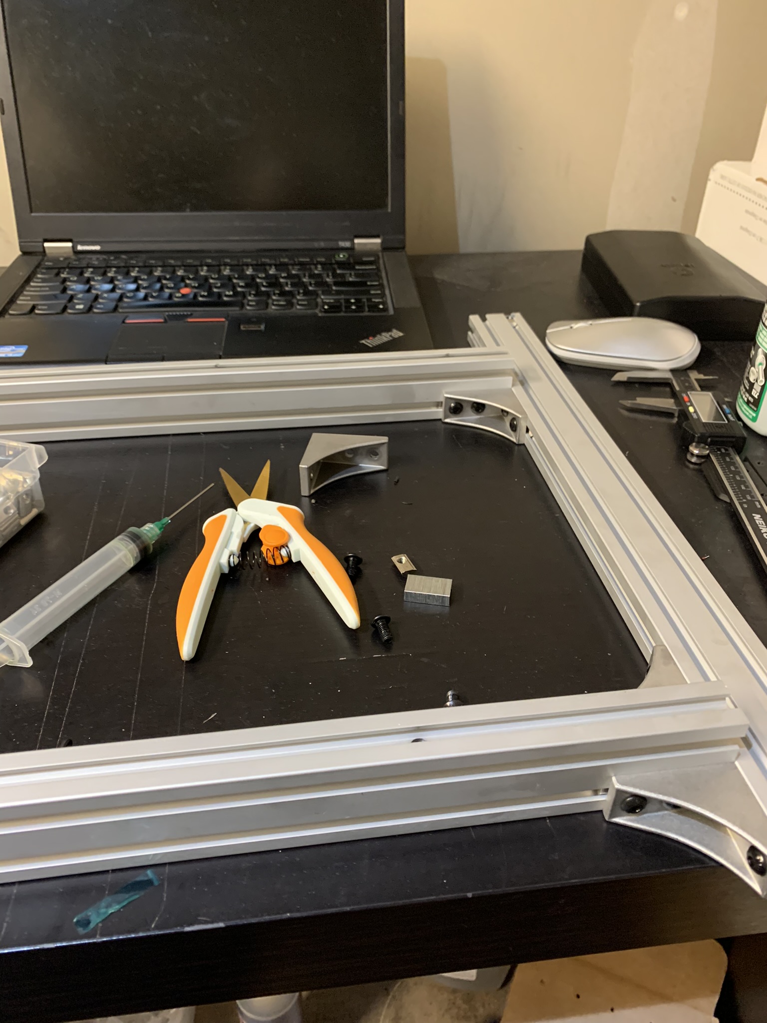
Figure 2: Extrusions attached at back left corner of the bed frame
Now attach the right extrusion to the frame, positioning it so that the external bracket is flush at the front right corner.
Attaching the bed frame
Adjust all four Z tensioners (this is why we left them loose in part four) so that they’re at roughly the same height.
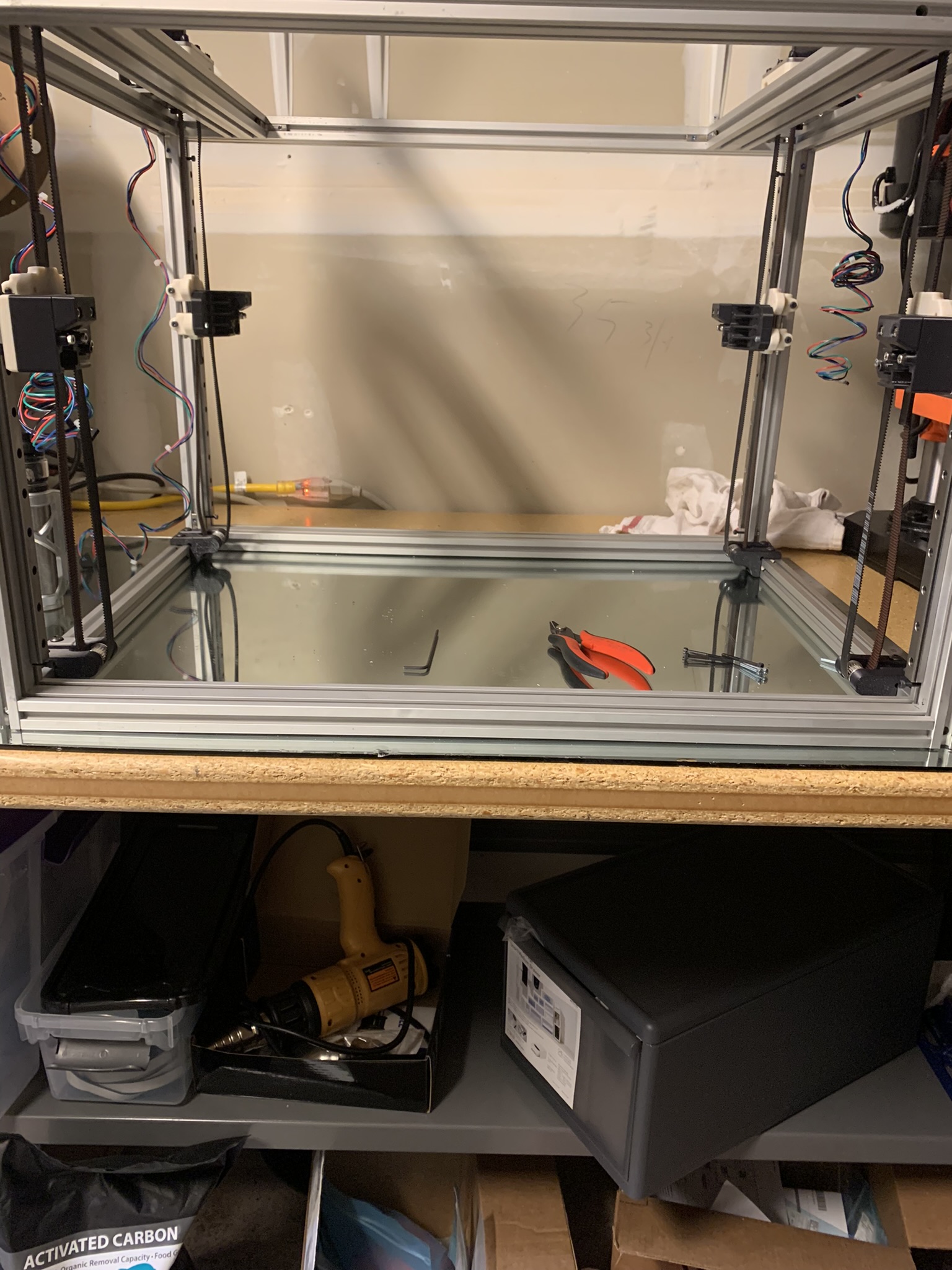
Figure 3: Z tensioners at roughly equal height
Lift the bed frame and set it gently on top of all four tensioners:
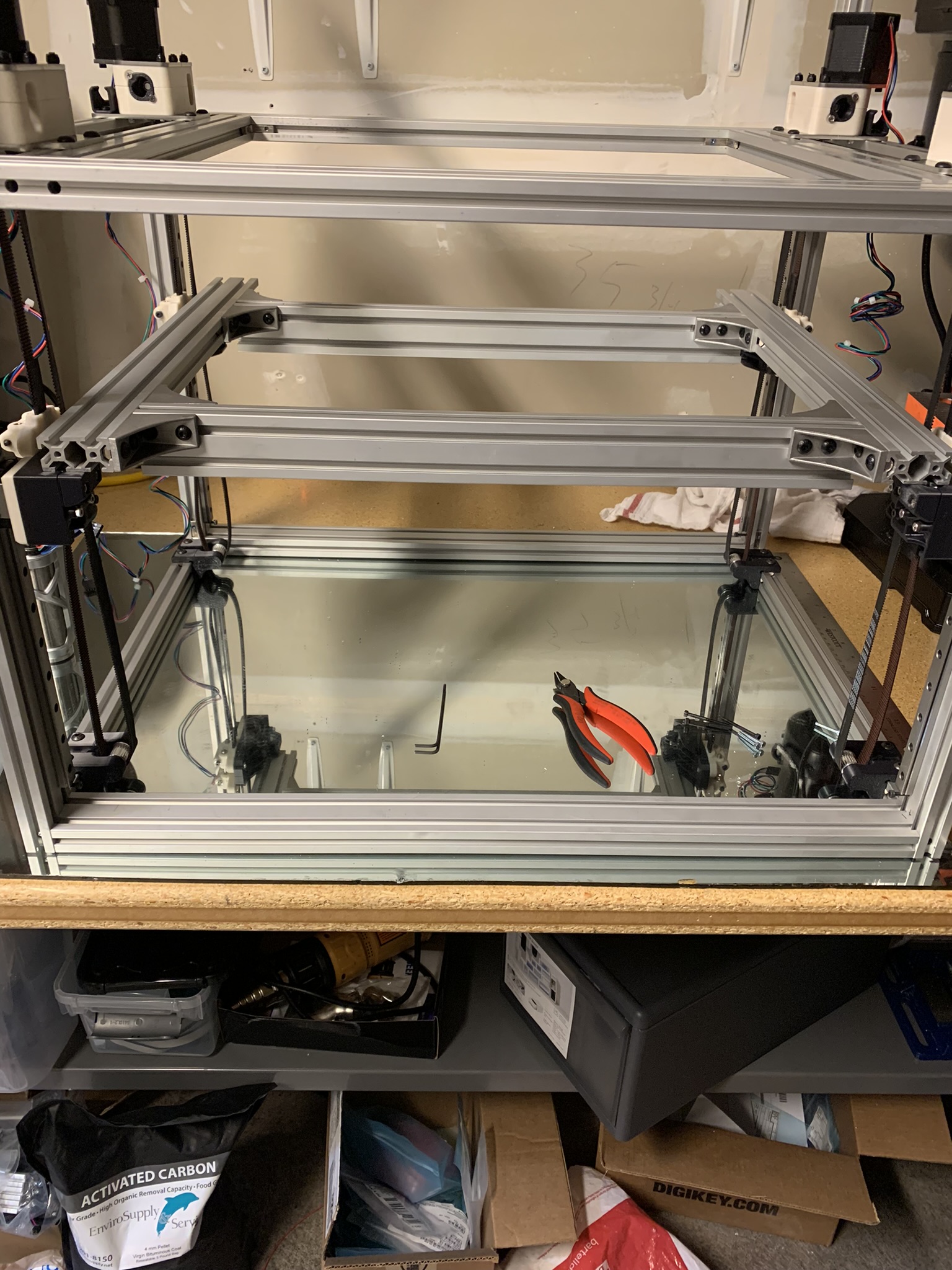
Figure 4: Bed frame resting on top of tensioners
Prepare 4x shoulder bolts with an M6x5 spacer each:
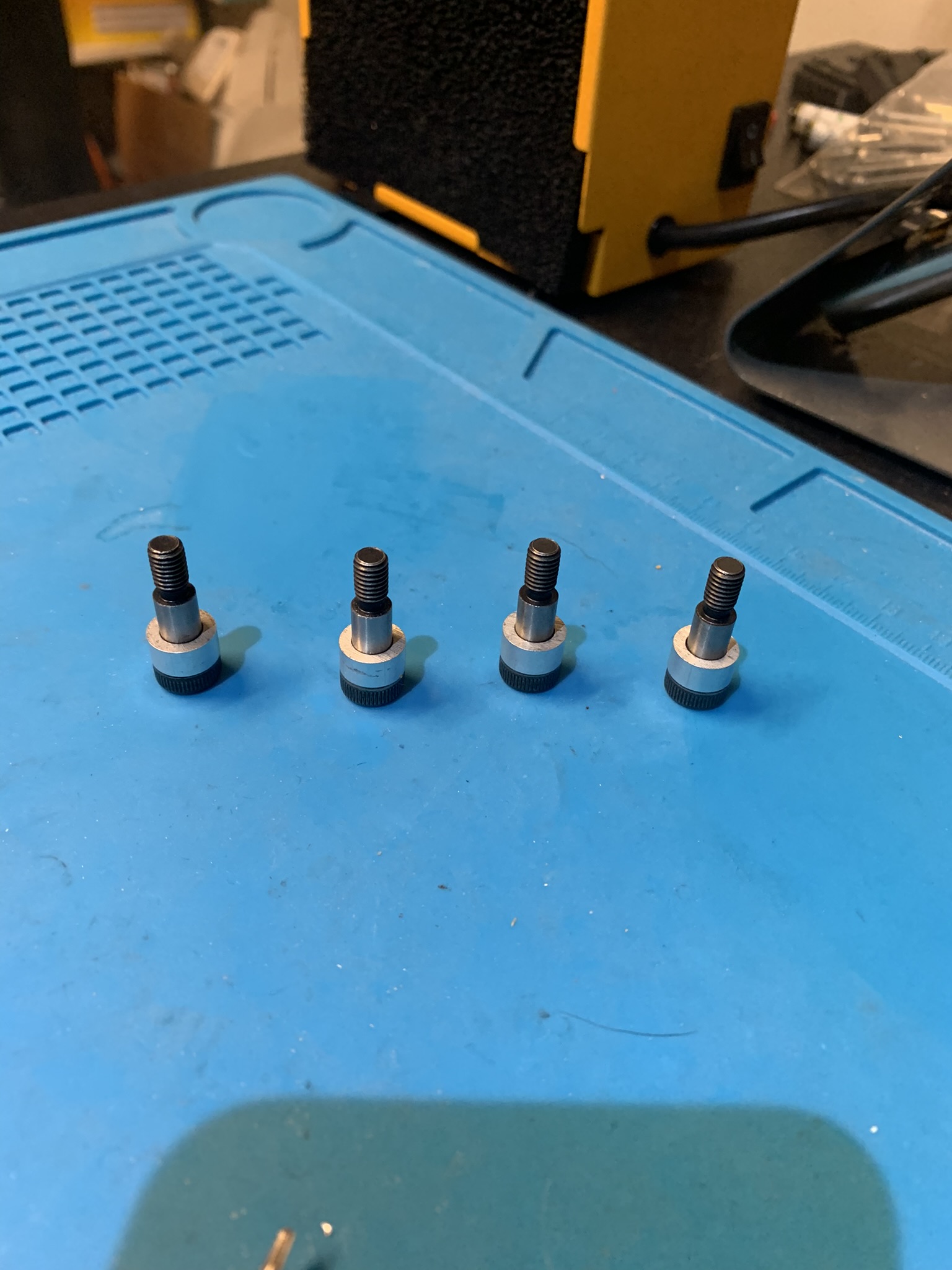
Figure 5: Shoulder bolts with M6 by 5 spacer on the bolt
Take one and insert it through the bearing inside the front left Z joint:
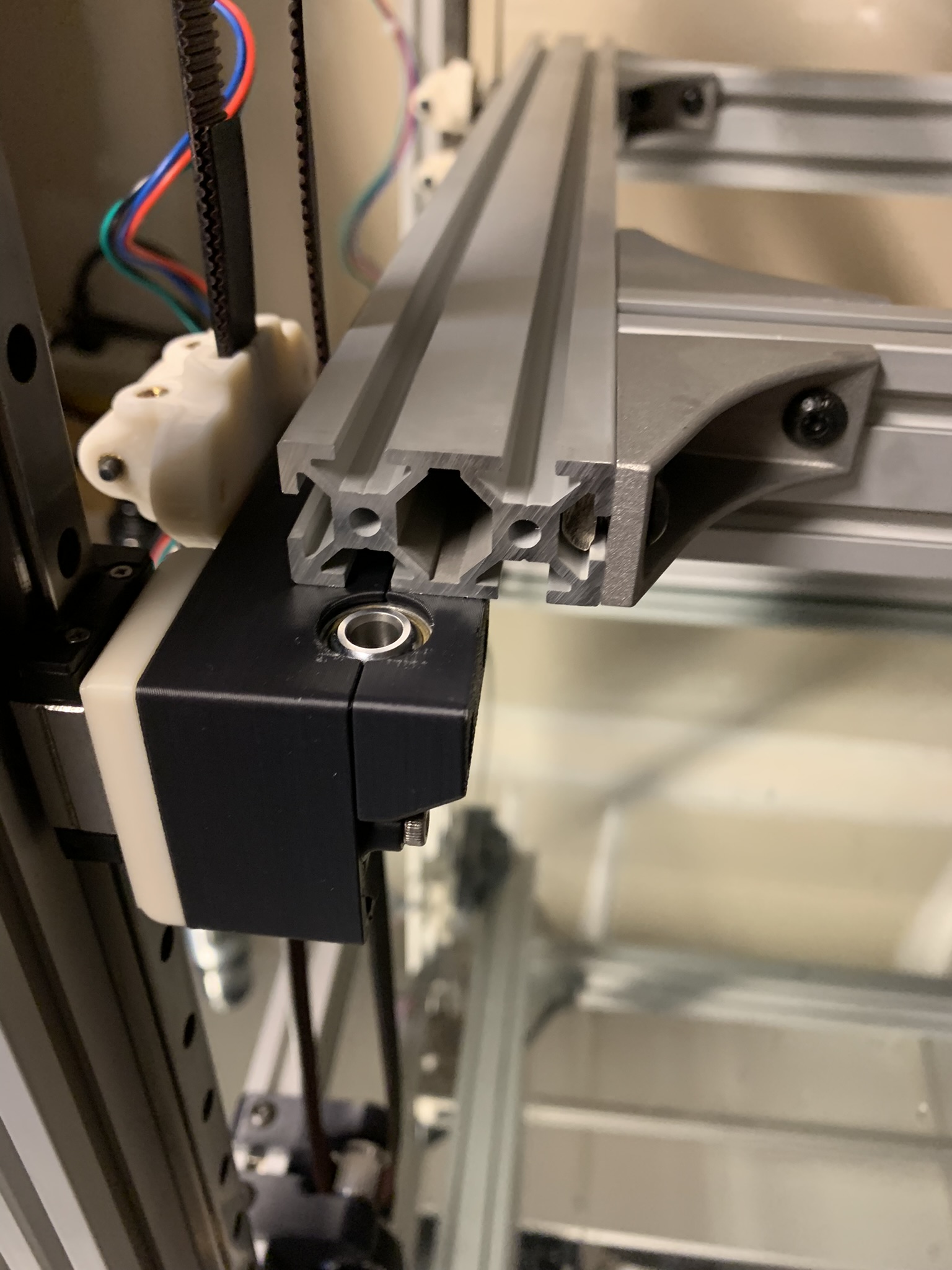
Figure 6: Bearing inside front left Z joint
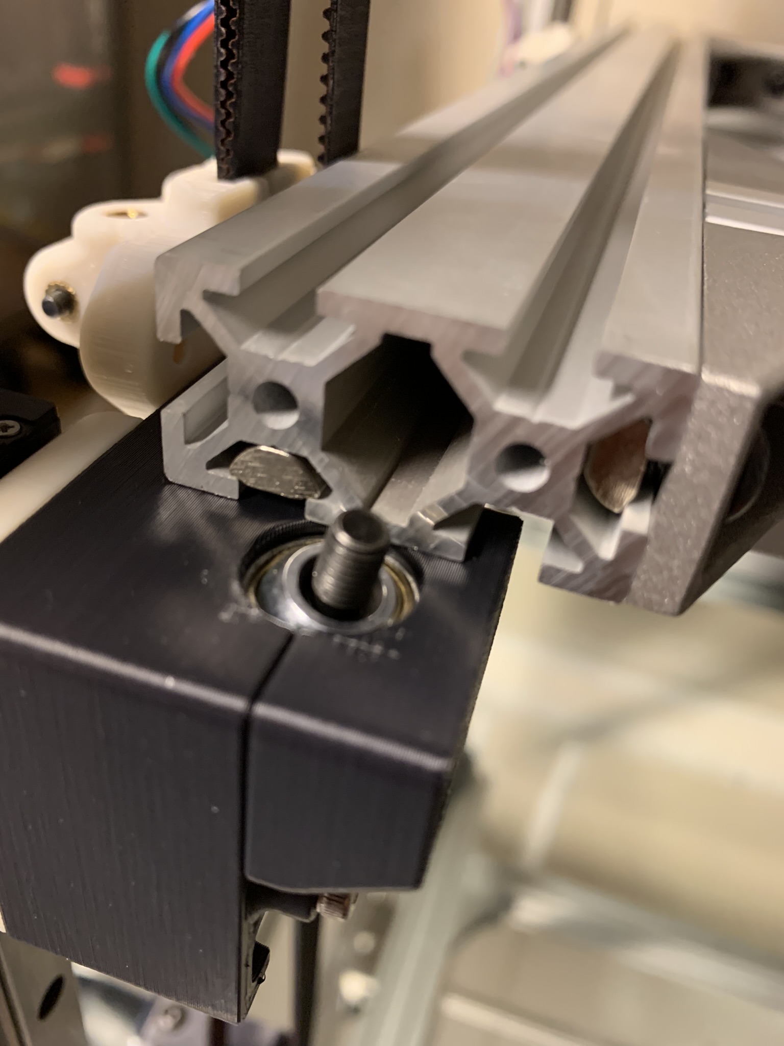
Figure 7: Shoulder bolt through the bearing inside front left Z joint
Insert an M5x3 spacer on top. Insert a roll-in nut into the outside slot of the left bed extrusion:
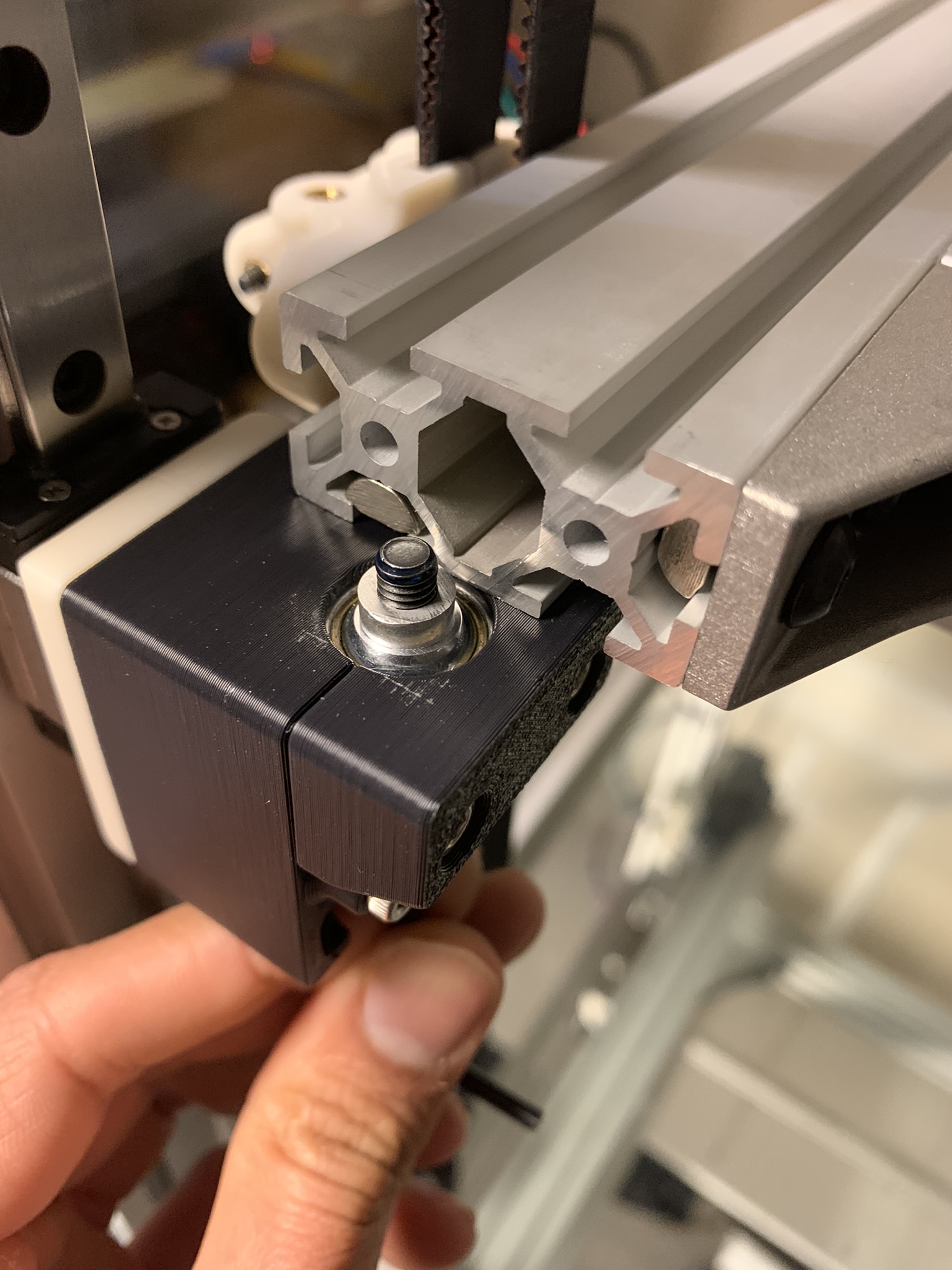
Figure 8: M5 by 3 spacer on shoulder bolt
Move the bed frame into position and screw the shoulder bolt into the roll-in nut. Repeat this process for the remaining three joints. The bolts should be snug but not very tight, we’ll tighten them after our first automated bed leveling.
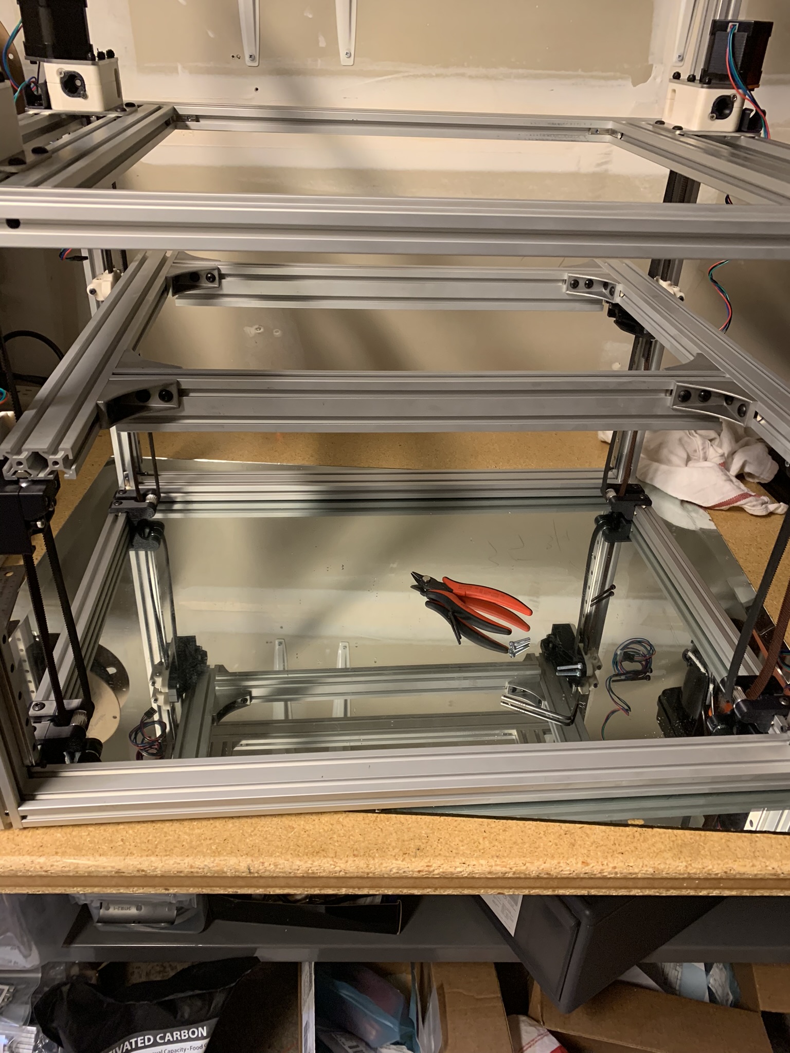
Figure 9: Bed frame, installed
Now that the bed is installed, we can tension our Z tensioners.
Bottom panel
Important note about the bottom panel and Z tensioning: With the current design of k2 (R2.1 with some experimental changes for R2.2), a bolted bottom panel is pretty much a requirement. Otherwise, tightening the Z tensioners makes Z idler extrusions rotate. This affects the belt alignment as well as belt tension. They eventually settle against the internal brackets, but there’s still more rotation than I’d like:
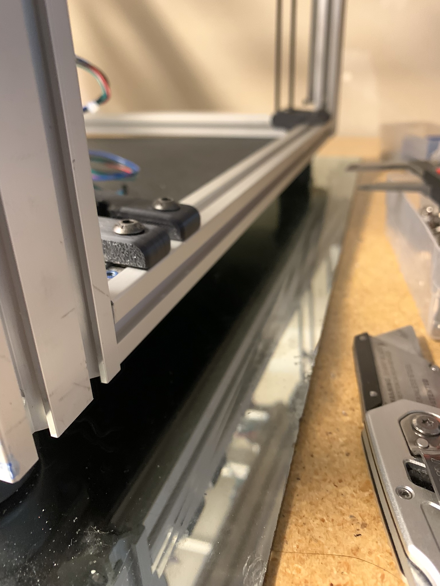
Figure 10: Extrusion that mounts Z idlers rotates when Z is tensioned
Using a bolted bottom panel combats this. I’ve opened an issue on Github about this, and the designers are trying to decide how to fix it, so the solution might be different when you’re assembling it. I encountered this issue after buying an ABS bottom panel, so I bought some external L-shaped brackets (linked below) to bolt the bottom extrusions together and used a dremel on my bottom panel to make it fit around the brackets. Whichever solution you pick - bolted panel or external bracket - make sure you constrain the bottom extrusions before you tighten the Z tensioners.
On to the build.
BOM
For each foot, you will need:
- 1x printed part
- 1x foot
- 1x M5 heatset
- 4x M5x10 BHCS
- 1x M5x20 BHCS or M5x16 SHCS (I didn’t have any M5x20 BHCS, and my M5x20 SHCS were too long. eDrawing says M5x20 BHCS but I have my doubts about whether it’ll fit)
- 1x L-shaped bracket, I used these from Amazon
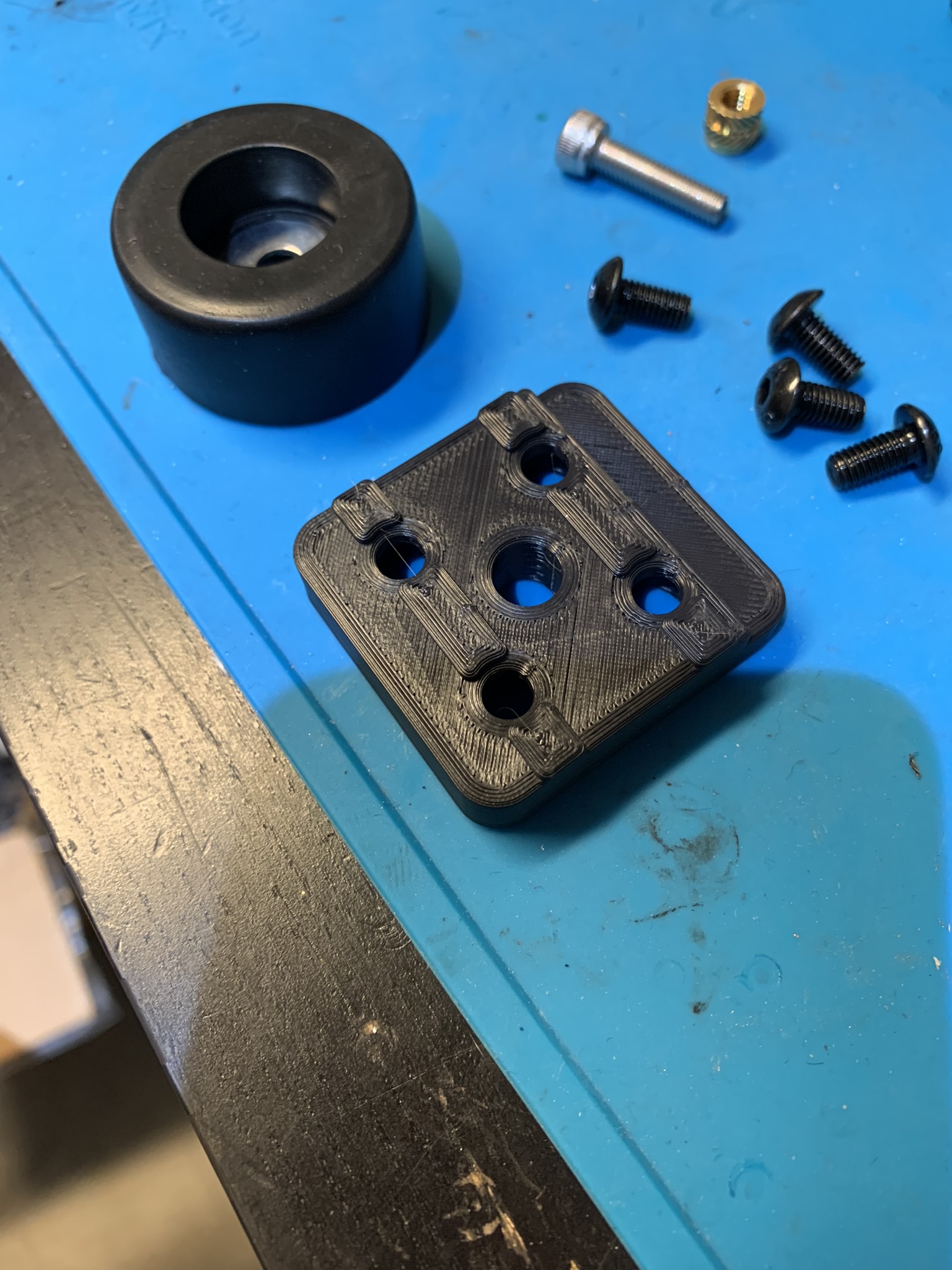
Figure 11: Bill of materials for feet
Install the heatset insert into the printed part:
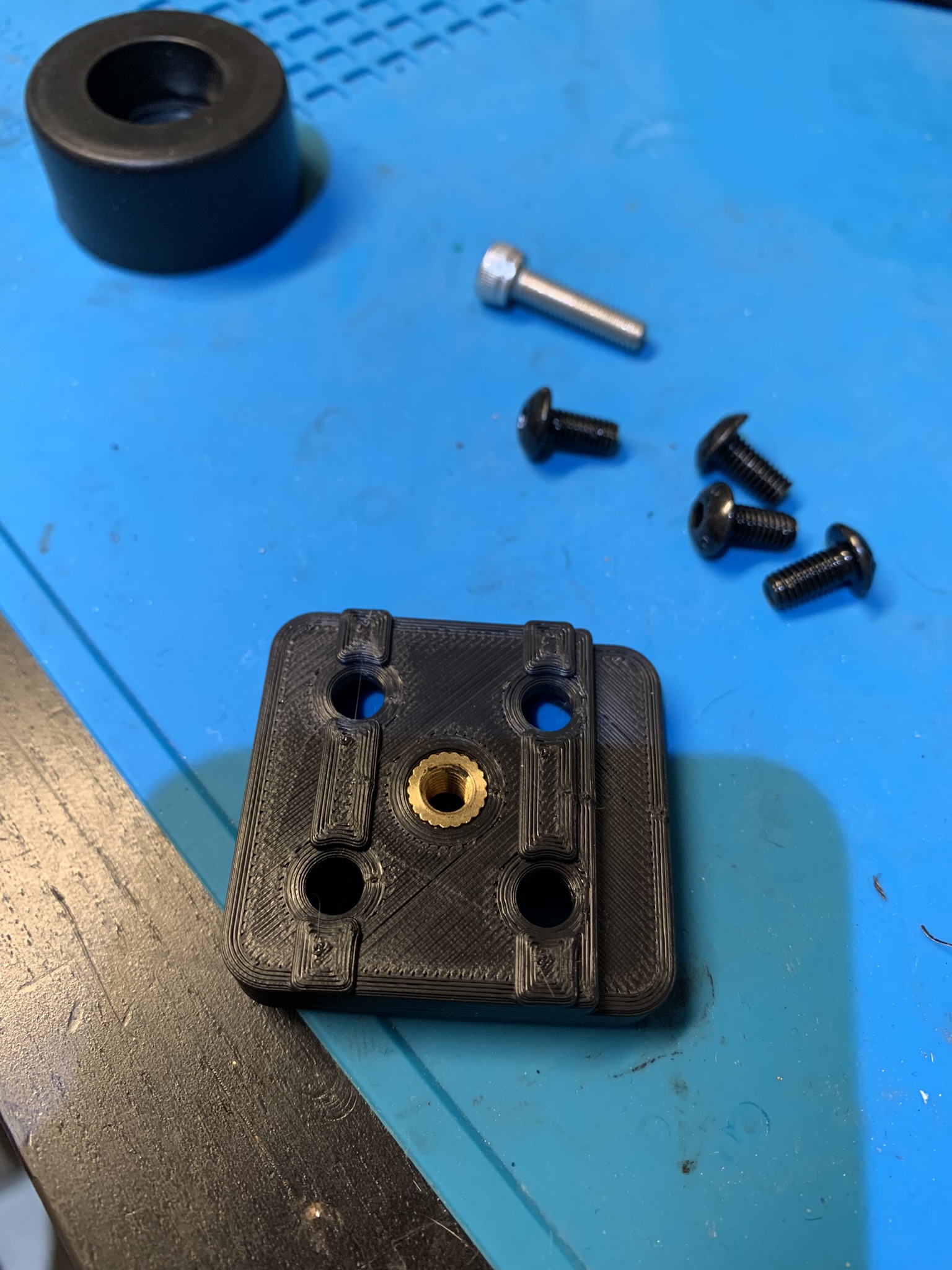
Figure 12: Heatset insert inside the foot’s printed part
Panel
If you’re using a bolted-on panel, use roll-in nuts and bolts to attach it to the bottom of the frame. Position four M5 roll-in nuts under the four holes at each corner of the panel. The feet will attach to the frame through those holes.
If you’re using an external bracket, install one in each corner now:

Figure 13: External L bracket attached to the bottom of the frame
Install the bottom two printed parts using M5x10 BHCS and roll-in M5 nuts. Mind the orientation: the printed part has a recess on one side that the panel sits in. Keep the bolts a bit loose and slide the panel into place. Using a sharpie to mark off the parts of the corners of the panel that you will need to shave off to make it fit around the L brackets. Take the panel off and use a dremel or another tool of your choice to remove the parts you marked, testing the fit as you go. Eventually, you’ll have a panel that fits. Attach it to the frame by putting on the top two printed parts:
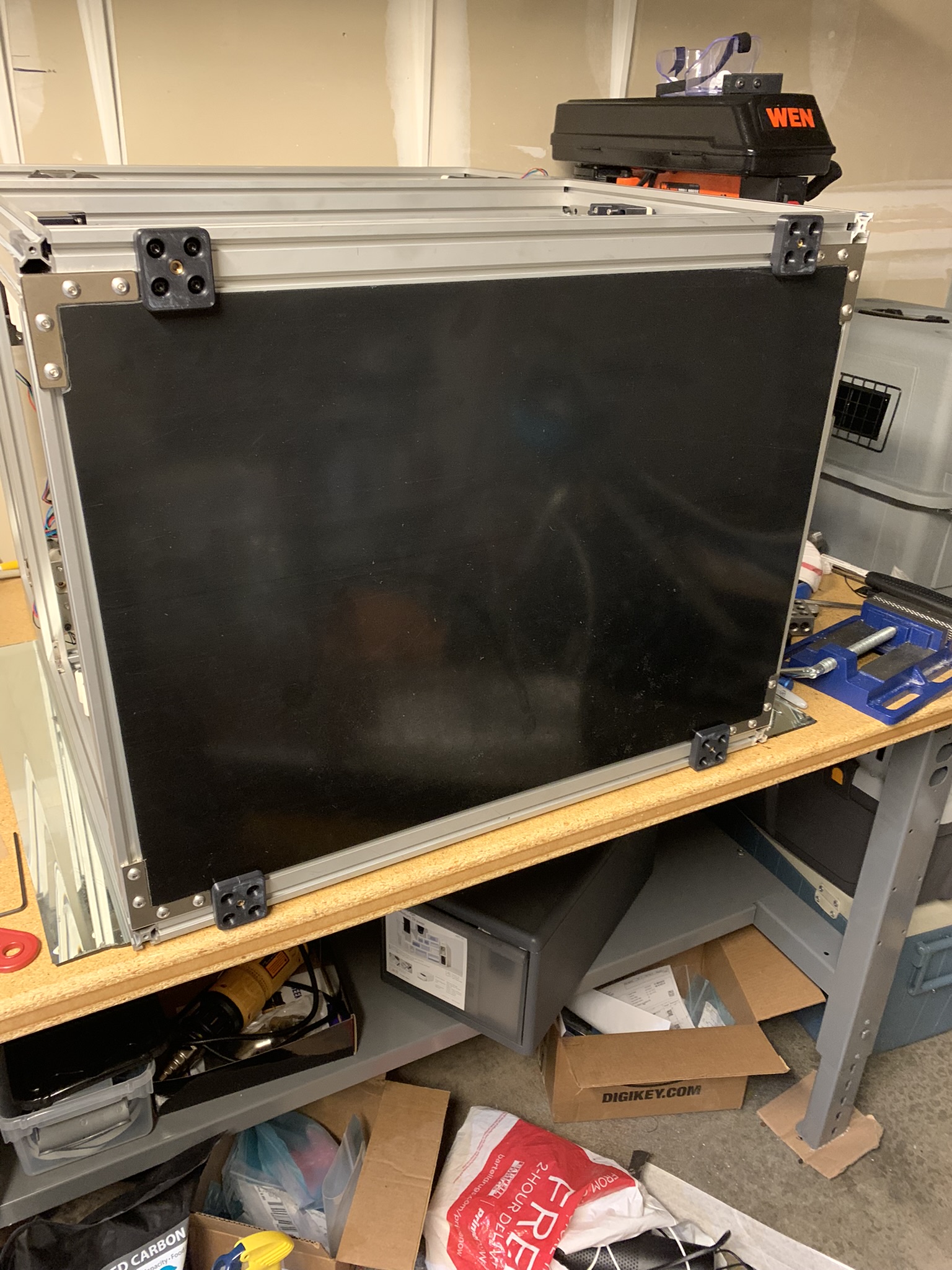
Figure 14: Bottom panel attached to the frame
Feet
Slide all the parts you installed as far towards the sides of the printer as they will go and tighten their bolts. Use M5x16 SHCS/M5x20 BHCS to attach the feet to the printed parts.
Tensioning Z tensioners
Pick a tensioner. Remove the left vertical bolt, apply loctite and screw it back in loosely. Do the same thing for the right bolt. Now tighten both bolts, alternating between them every few turns until the two halves sit flush with each other:
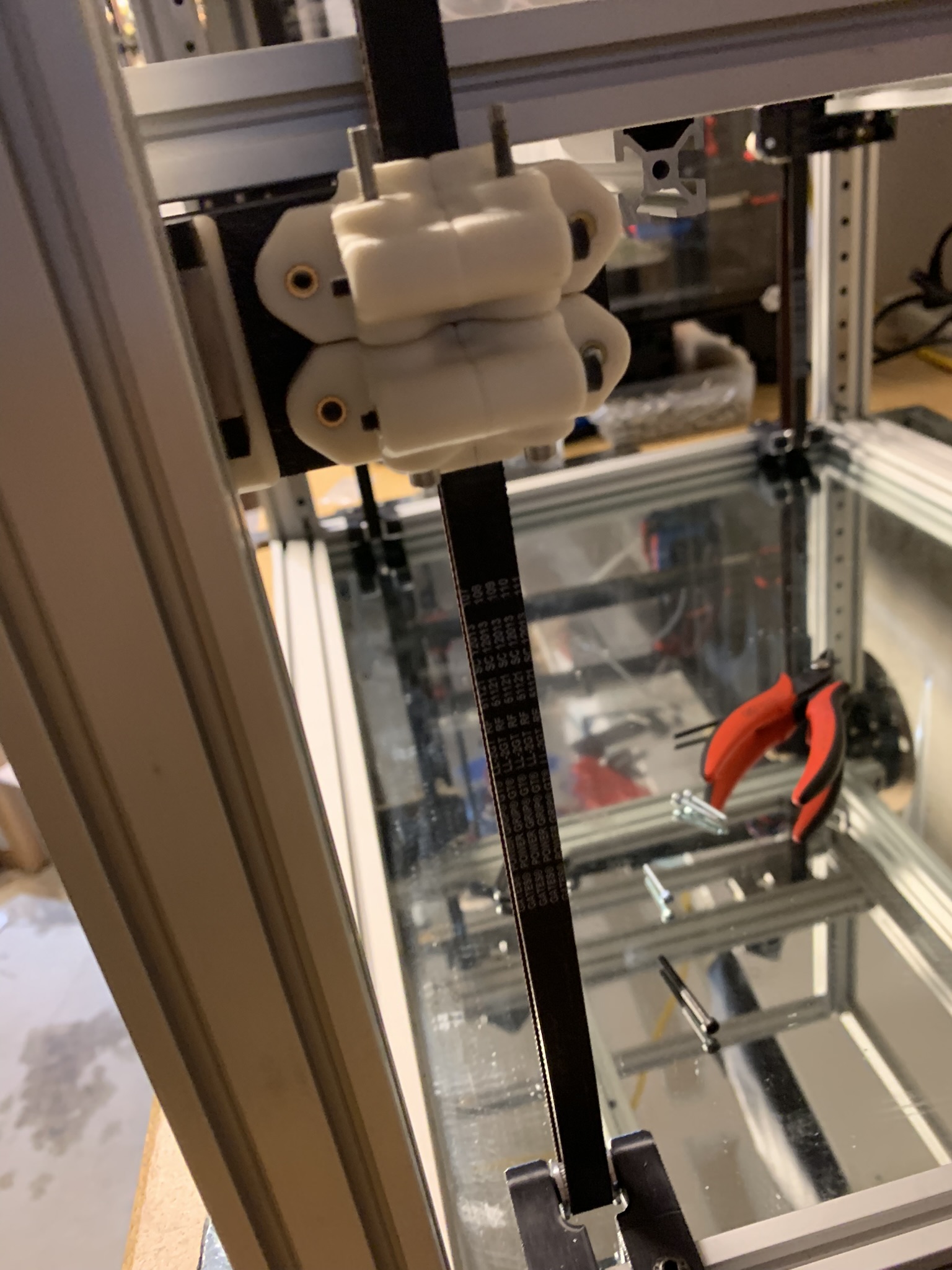
Figure 15: Z tensioner with bolts tightened
Apply loctite to 1x M3x20 SHCS and 1x M3x35 SHCS and attach the top half of the tensioner to the bed lifting part.
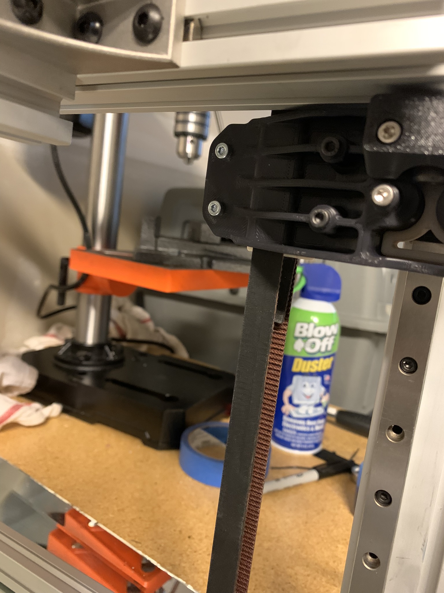
Figure 16: Z tensioner with top half attached to bed lifting part
Here’s what it looks like from the other side:
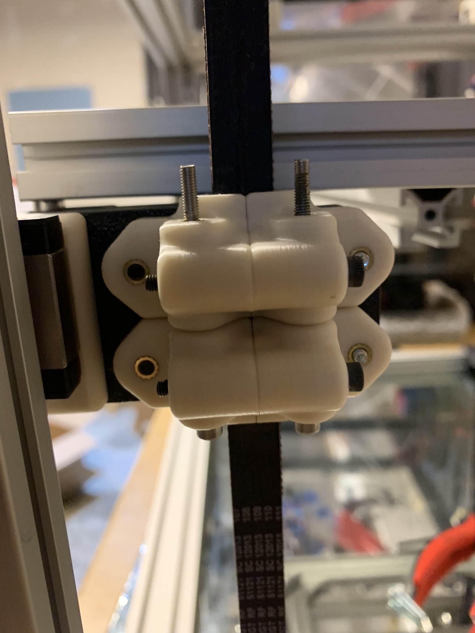
Figure 17: Z tensioner with top half attached to bed lifting part, opposite angle
Repeat for the other three tensioners. We’re done with the Z portion of the build.
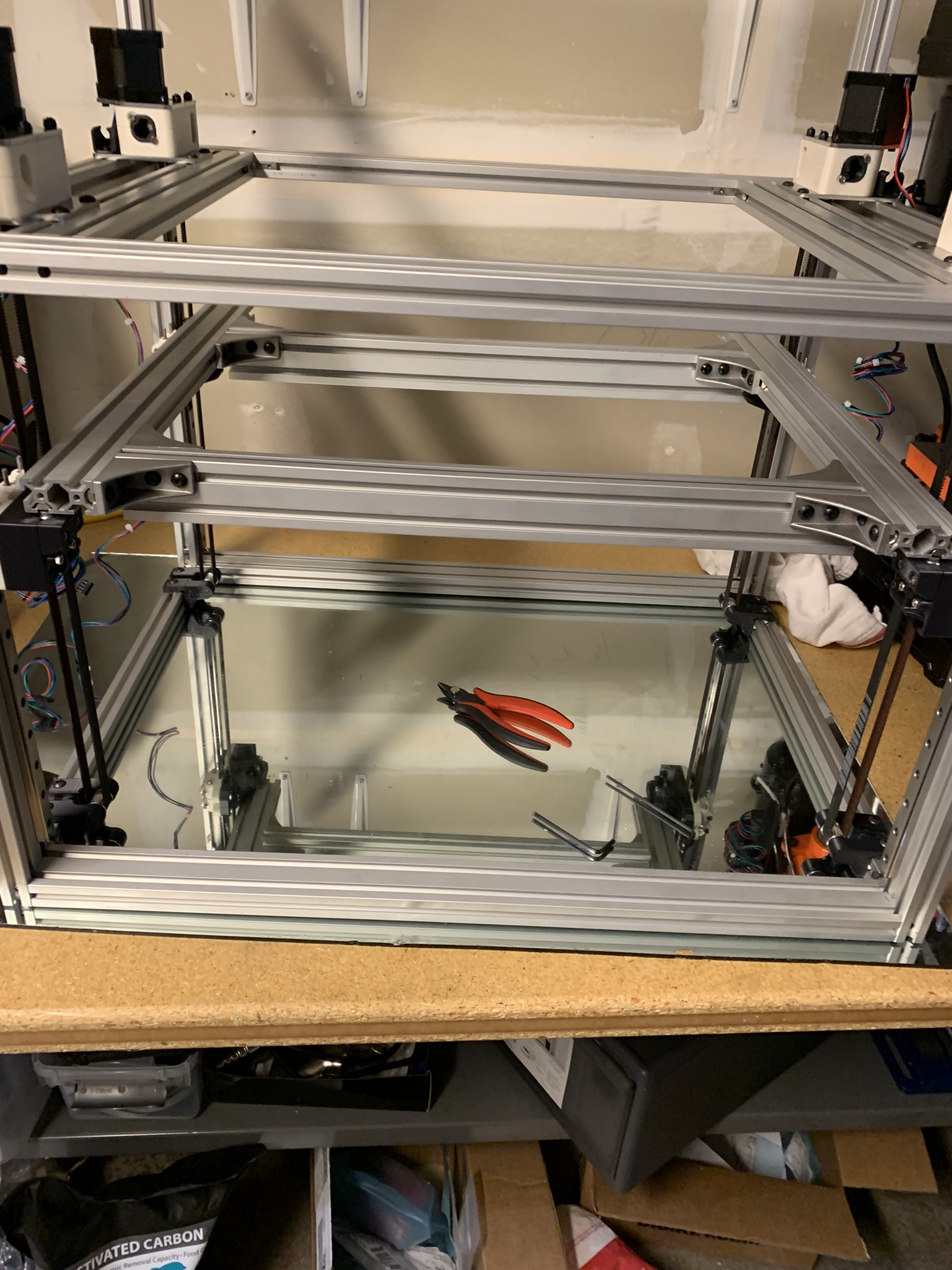
Figure 18: Z tensioner with top half attached to bed lifting part, opposite angle