K2 Build Log Part Ten: Wiring Part One
Apr 7, 2022⚠️ DISCLAIMER - Incorrect wiring can pose a serious health risk. The instructions in this post are my effort to be helpful, but they should not be taken as expert device. I accept no responsibility for any damages you might experience by following these instructions.
You could choose to finish all wiring before turning on your printer. I recommend that you not do this, and instead test things incrementally. I chose to keep my printer powered off while wiring things, and then would turn it on to test each new thing that was wired up. I also took a break once all my gantry and Z motors were wired up, and buzzed them to verify my wiring and their directions. As such, I’ve split up wiring into two parts, with an intermission in the middle for motor testing.
Mains inlet and rocker switch
Make sure you use wires of a sufficient gauge. I used 18 awg for all wires connected to AC or 24V DC.
Crimp insulated spade connectors onto wires and connect the L and N plugs of the inlet to the rocker switch. It’s important that you connect them to the plugs in the lower half of the switch as shown in the picture below.
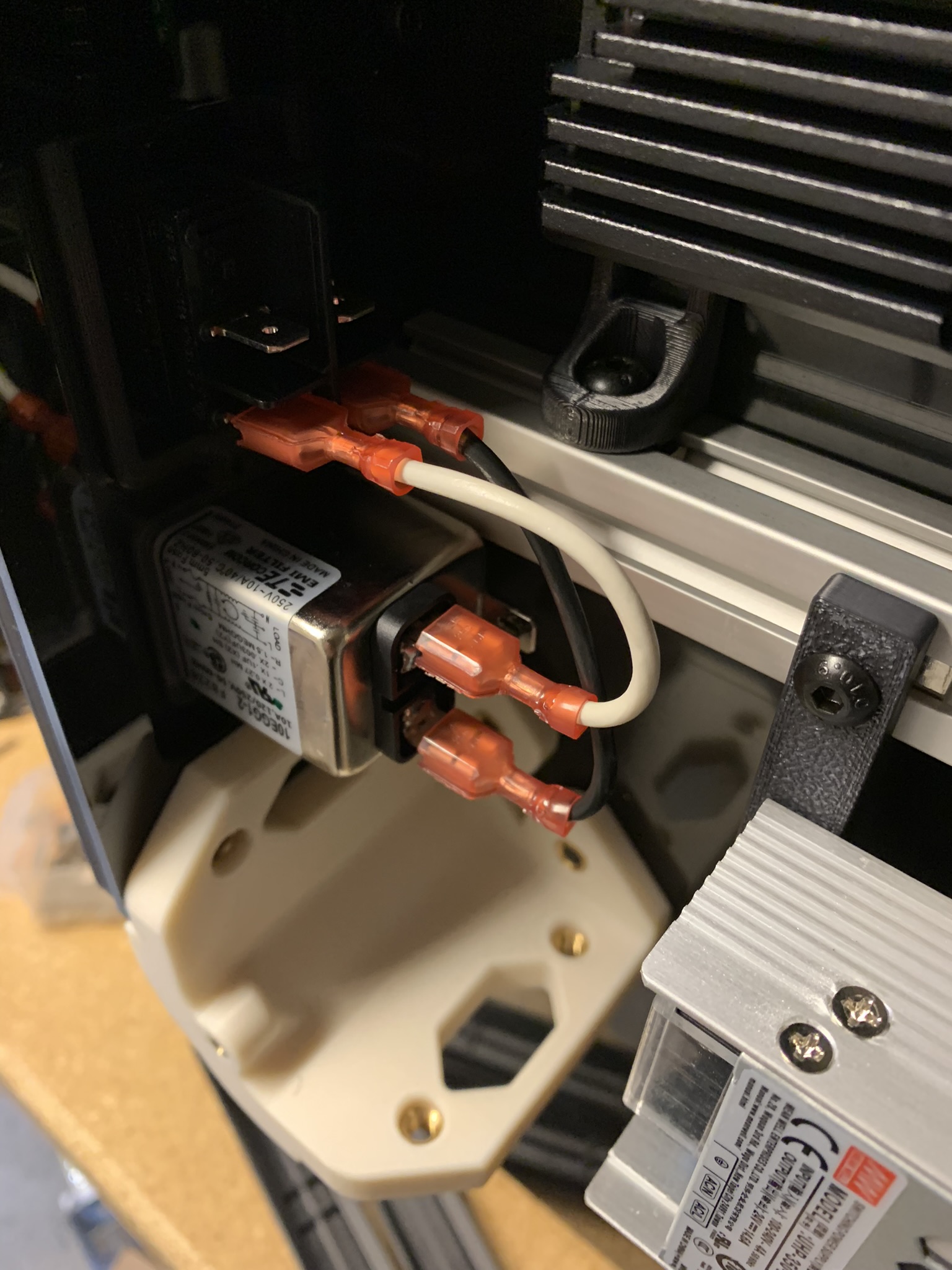
Figure 1: Wires connecting the mains inlet and rocker switch
Connect the plugs in the upper half of the switch and the ground plug to the mains WAGOs. Important things to note here:
- Be consistent with colors. I picked White for Live/Load, Black for Neutral, and Green for Ground. Note the colors of wires coming into the rocker switch and exiting it.
- I was told on the Annex discord that AC works by detecting the difference between input signals, so there’s no real “Live” or “Neutral”. As such, treat all mains wires as being LIVE.
- Strip about 1 inch off wires that go into WAGO terminals. As far as I know, it is recommended that you not twist the strands before inserting them into the terminals.
UHP PSU input wiring
The UHP PSU I bought does not have an input voltage selector. Check if yours has an input selector switch, and choose the right input voltage if it does.
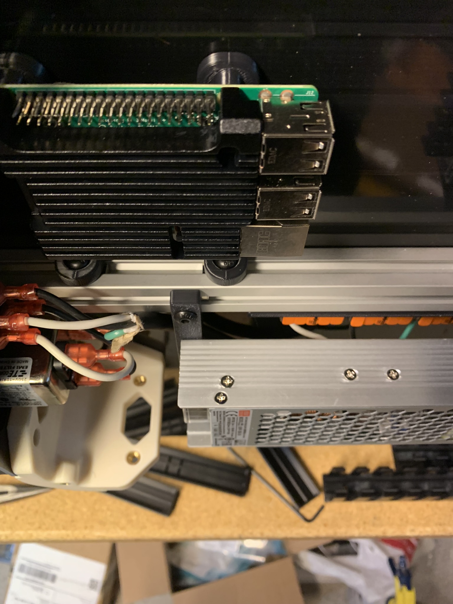
The BOM has two different kinds of fork spade terminals. Pick the kind that fits your terminals. I had to use the ones on the right for UHP inputs and the ones on the left for UHP outputs.
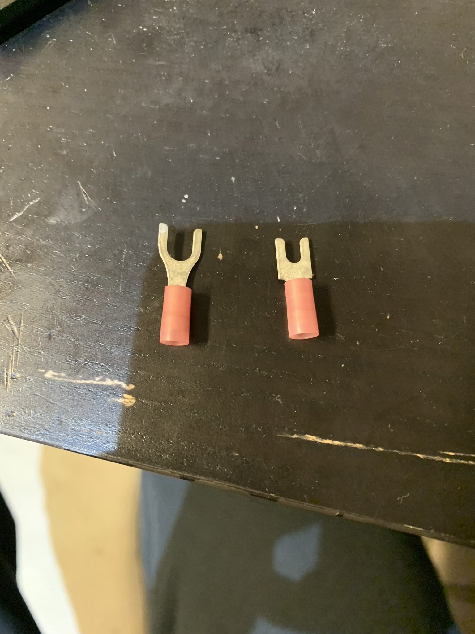
Figure 2: Two kinds of fork spade terminals
Connect L, N and G wires from the mains WAGOs to the UHP power supply.
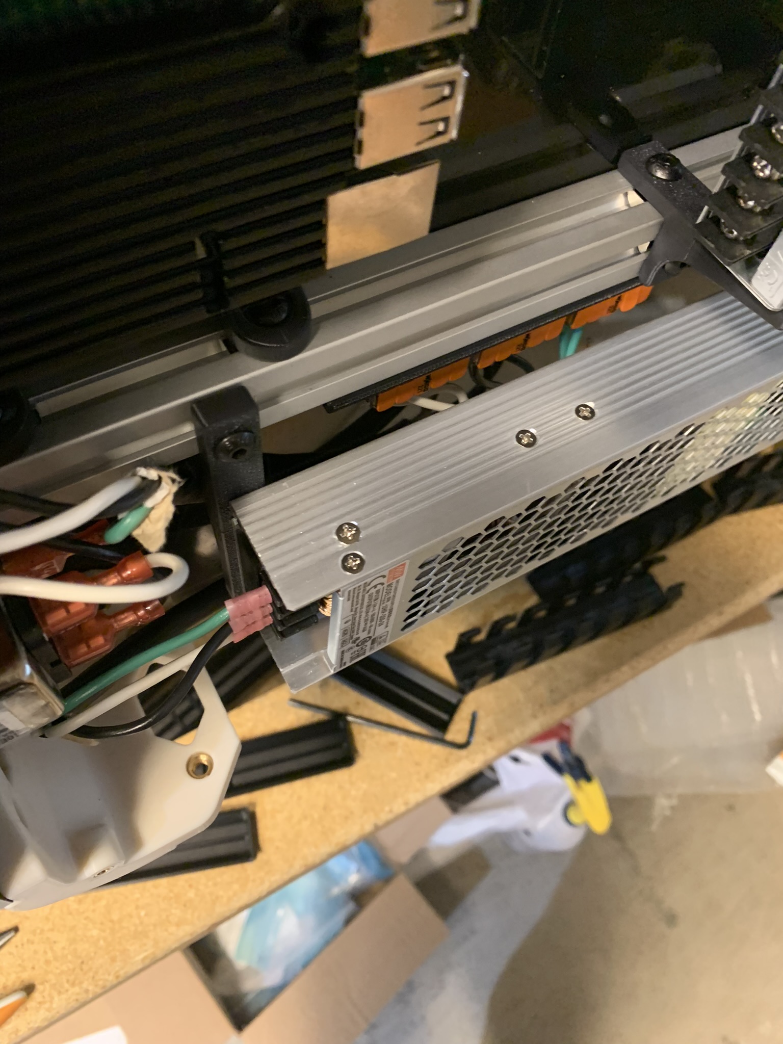
Figure 3: Wires connected from main WAGOs to the UHP inputs
Place the terminal cover on.
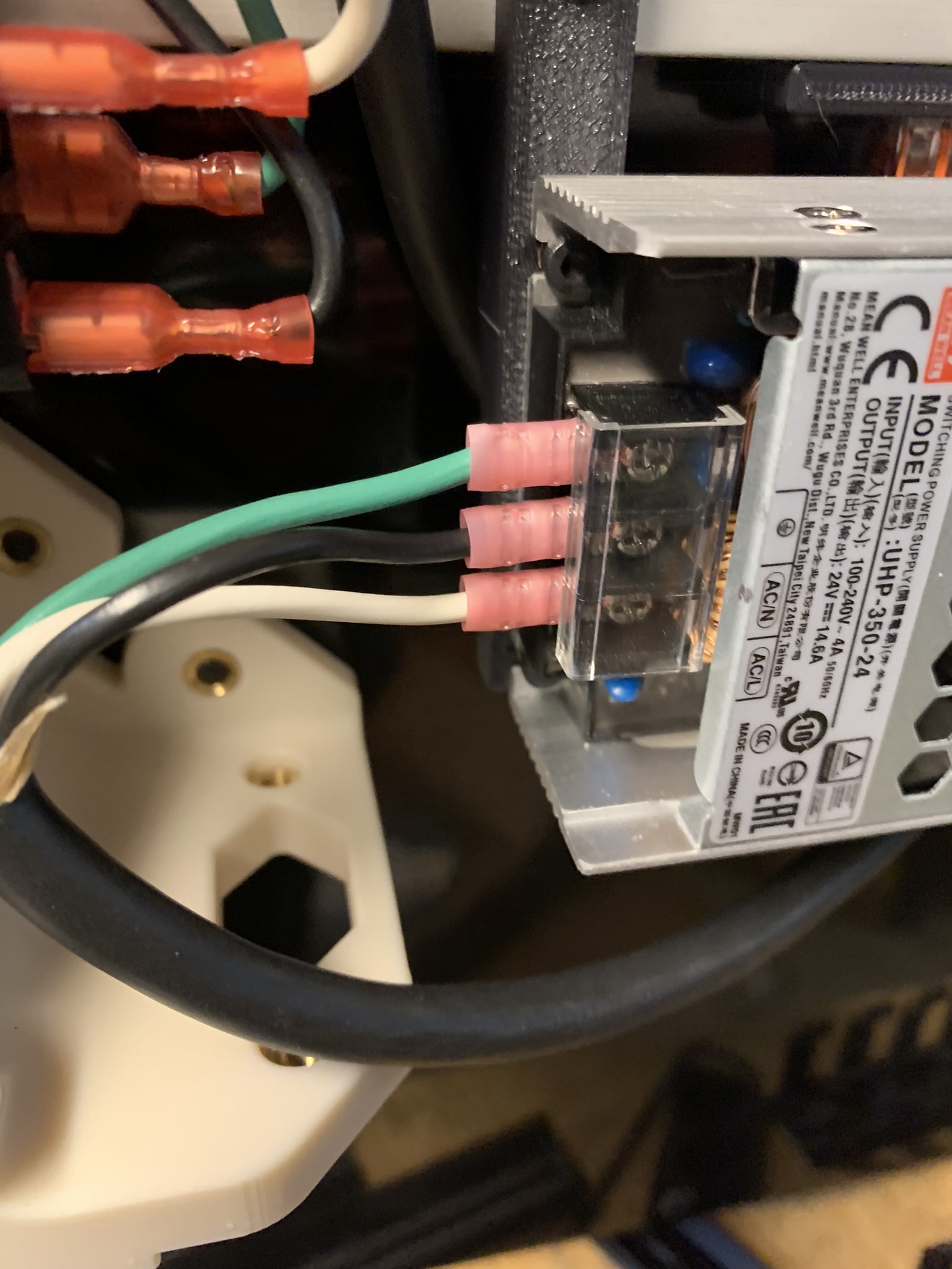
Figure 4: Wires connected from main WAGOs to the UHP inputs, close-up
Double-check all of your wiring so far and then power on the printer. Verify that the green light on the power supply turns on.
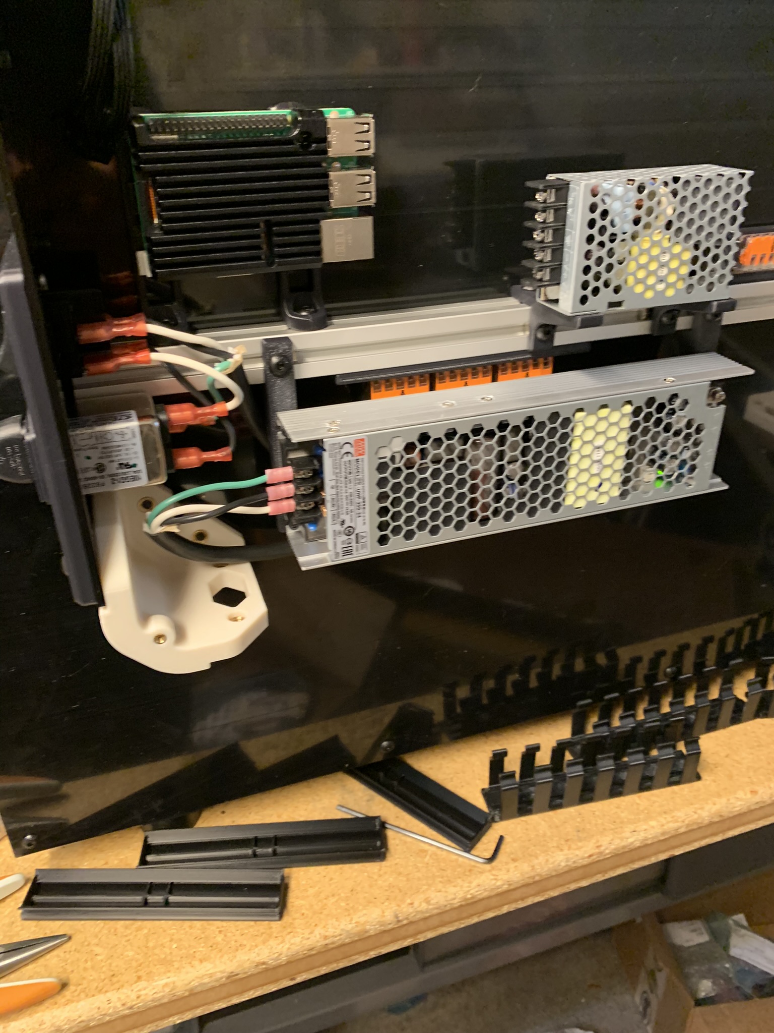
Figure 5: UHP power supply powered on
Turn the printer off before proceeding.
RS input wiring
Connect L, N and G wires from the mains WAGOs to the RS power supply.
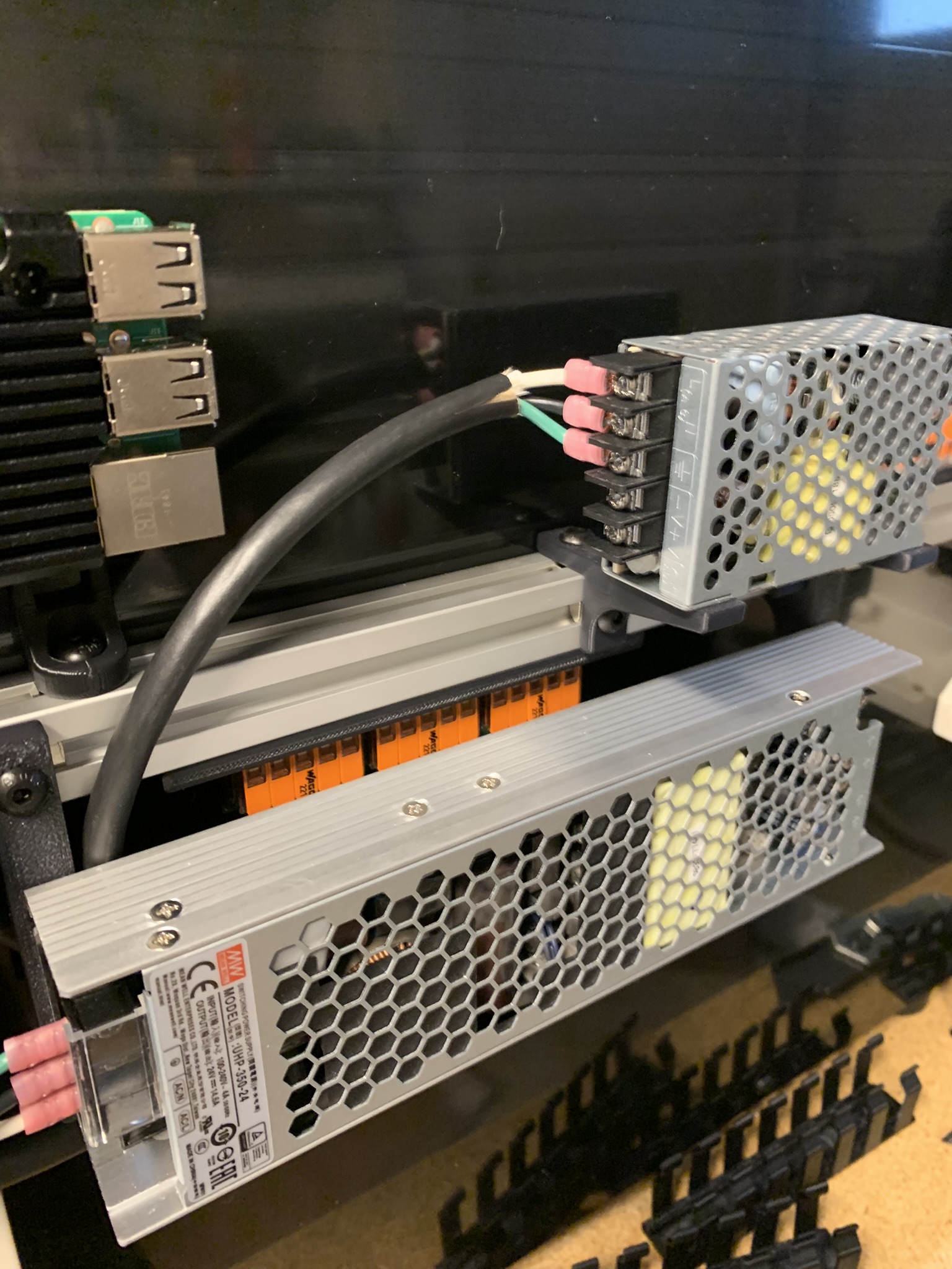
Figure 6: Wires connected from main WAGOs to the RS inputs
SSR input wiring (partial)
Connect L to terminal 1 of your SSR. Terminal 2 will be connected to the bed later.
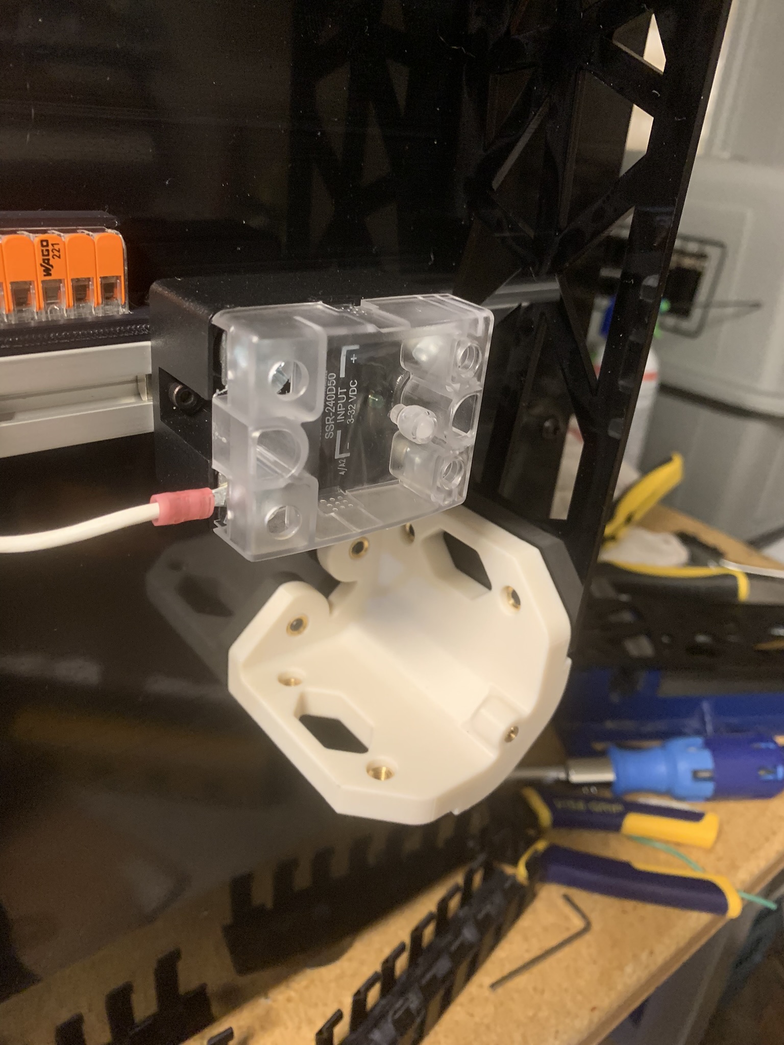
Figure 7: Wire connected from main WAGOs to the SSR
Controllers DC input wiring
Connect wires from the UHP PSU outputs to the 24V WAGOs. Connect wires from the 24V WAGOs to your controllers (and expander if you have one). Refer to the labels on your controllers and ensure you’re connecting + to + and - to -. Use Ferrule connectors for the ends going into the controllers.
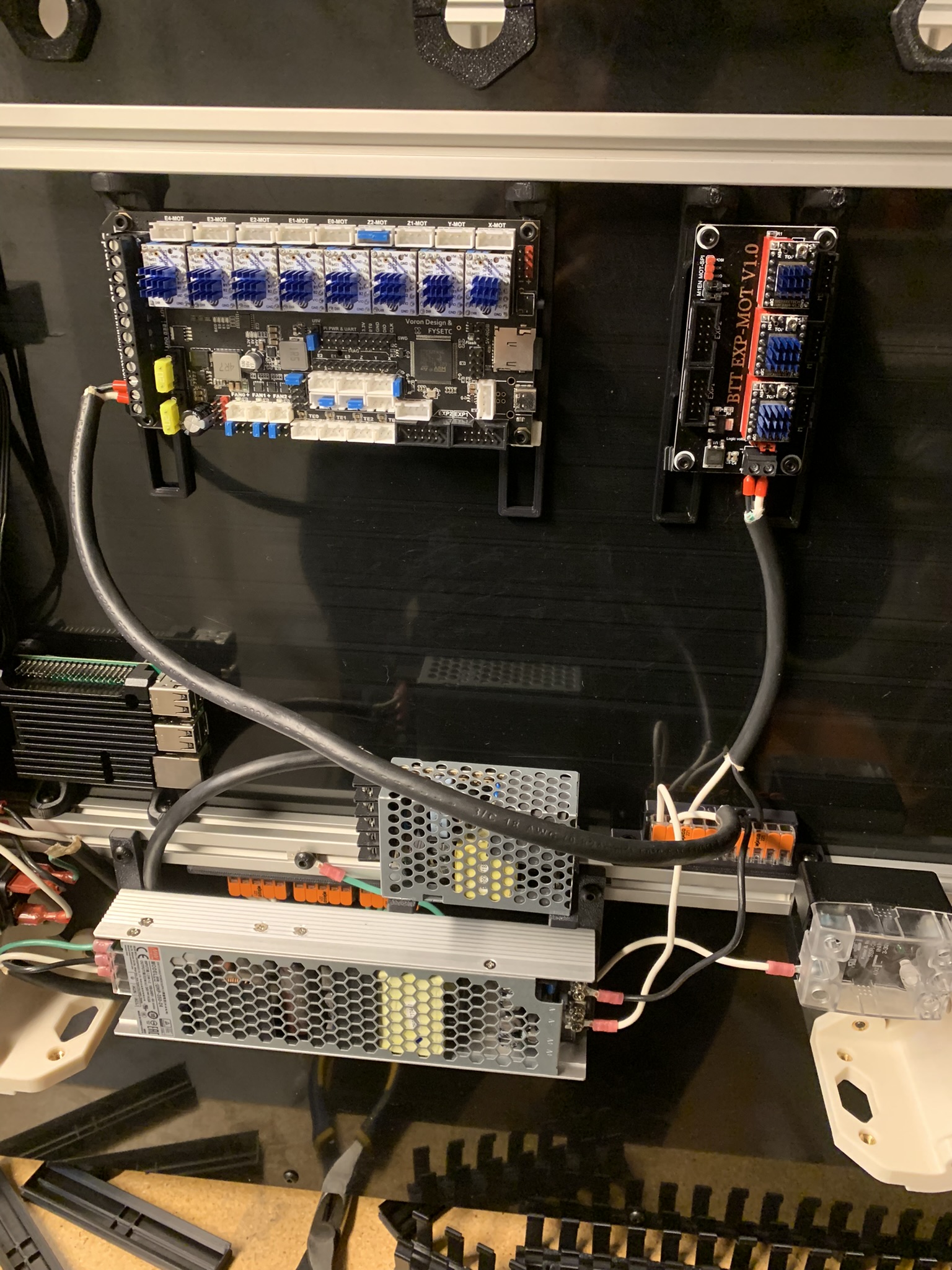
Figure 8: DC inputs connected to controller and expander
Double-check all of your wiring so far and then power on the printer. Verify that the controller and expander power on.
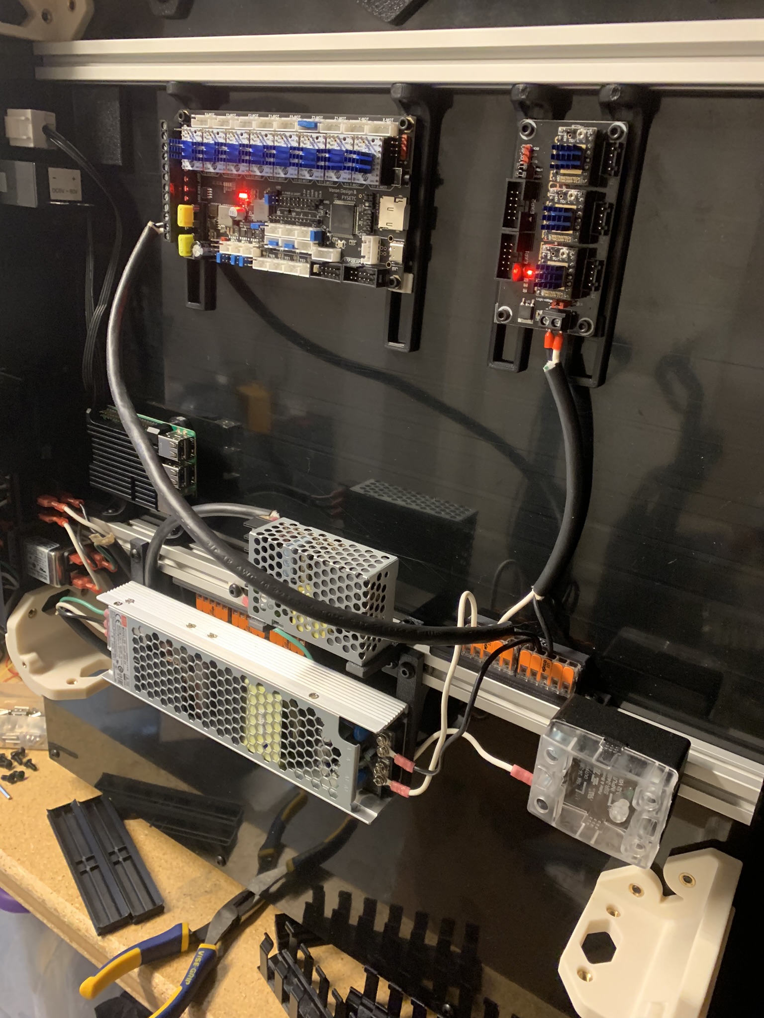
Figure 9: Controller and expander powered on
Turn the printer off. Connect ribbon cables from your controller to your expander. For a Spider v1, I had to connect EXP2 to EXP1 and vice versa, and I had to connect them upside down at the expander end. You should check the pinout for your controller and expander to determine whether swapping and/or flipping is necessary for you.
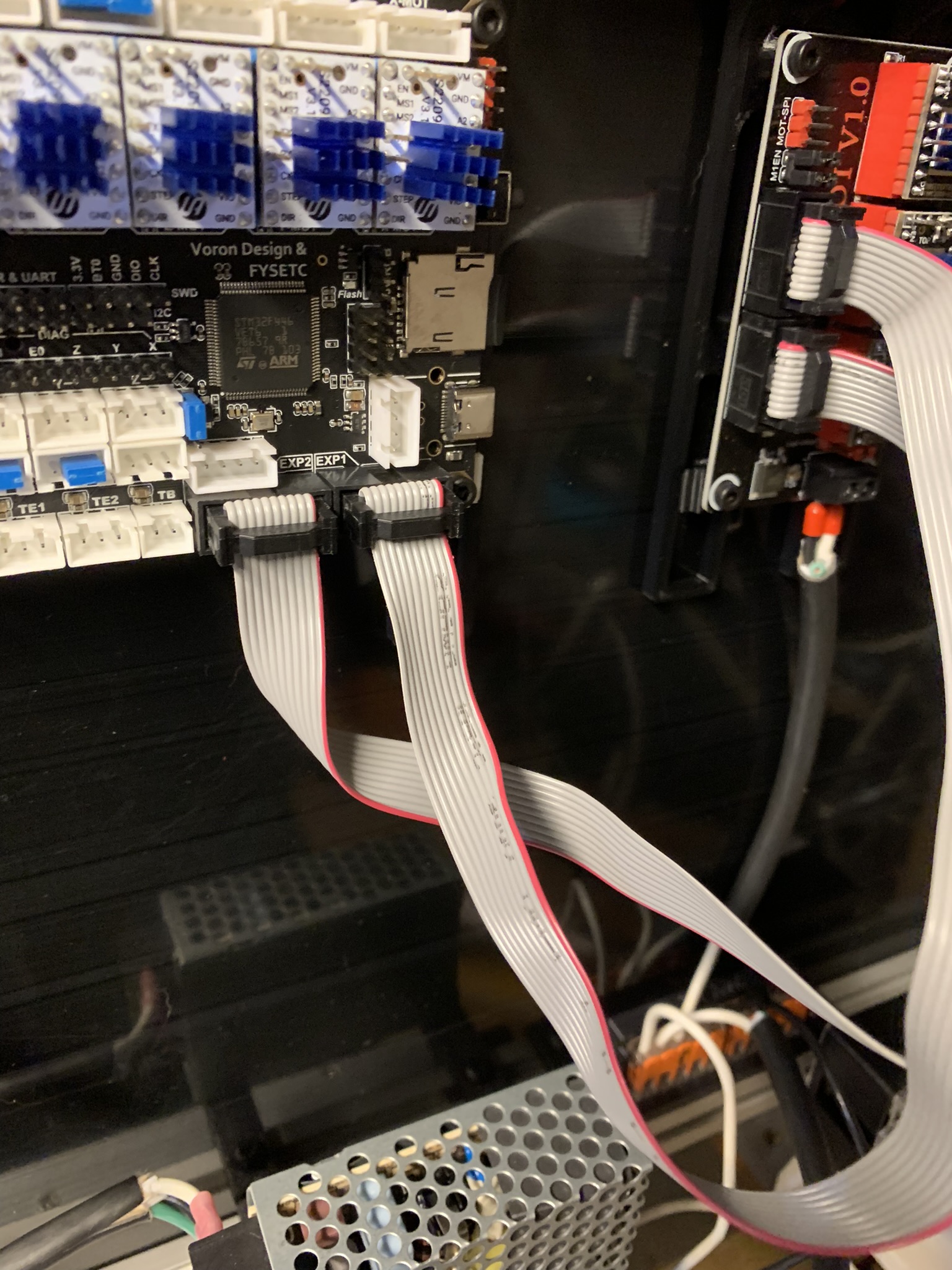
Figure 10: Controller and expander connected by flat expansion cables
Pi input wiring
Connect a micro USB cable to the input of your Pi, determine how long it needs to be in order to reach the output terminals of your RS PSU, and cut it at the right length. If you have fork spade terminals that are the right size, you can crimp the ends. I didn’t have small enough spade terminals, so I just stripped the insulation and screwed the bare wires into the RS PSU’s output terminals.
As before, double-check all wiring and power on the printer. Verify that the Pi powers on, and then turn the printer off.
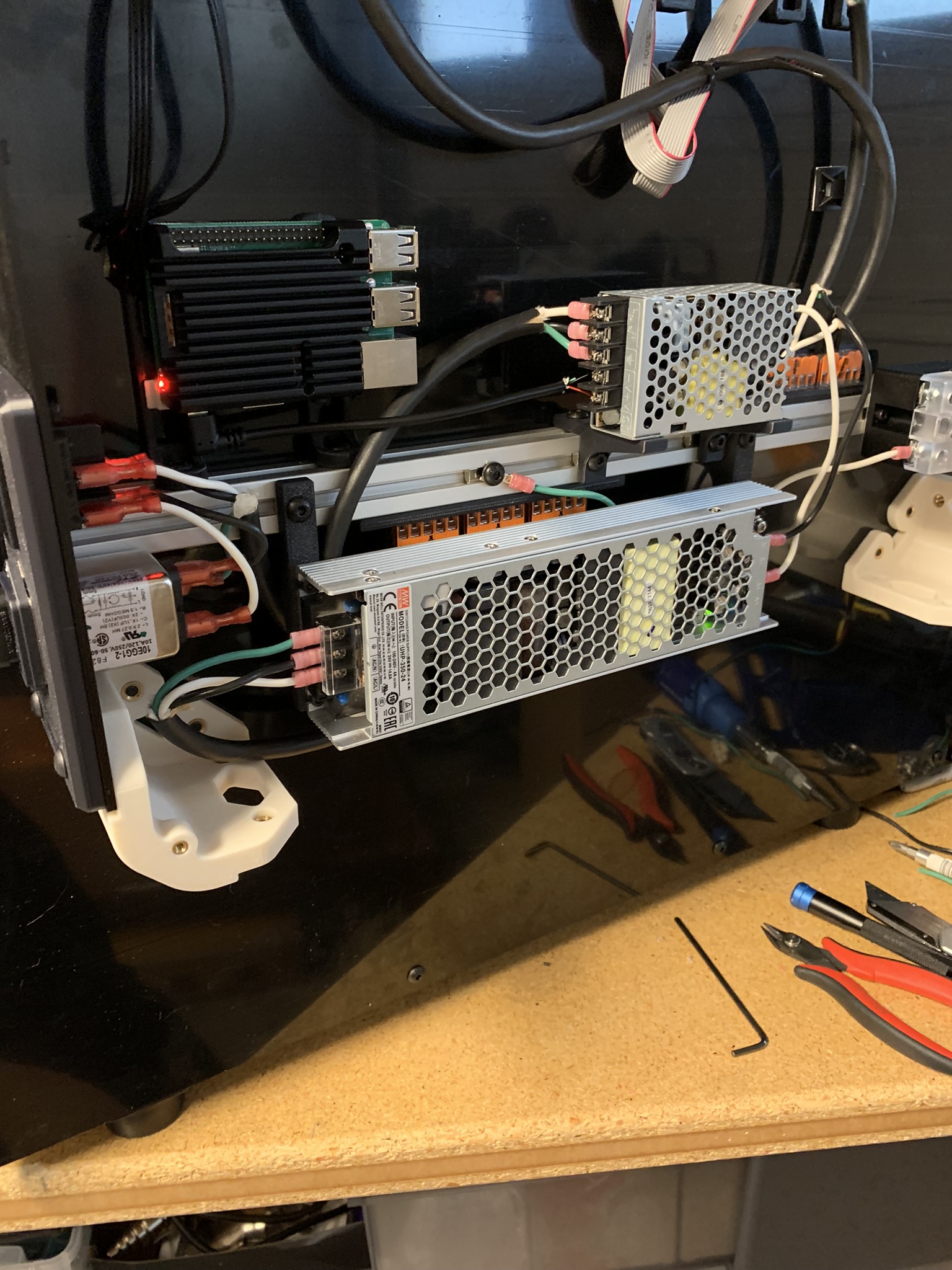
Figure 11: Pi powered on
Ignore the green wire bolted to the extrusion in the above picture. I had grounded that extrusion, but then realized that I didn’t have enough ground WAGO terminals left to ground the main printer frame and the bed, and grounding those is paramount, so I took it off later. Connect your controller(s) to the Pi using USB cables. The expander doesn’t need to be connected to the Pi, it communicates instead with the controller that it expands.
Motor wiring
Here’s an overview of how the motors are named in the klipper config and where they’re all located relative to the front of your printer. This is a top-down view:
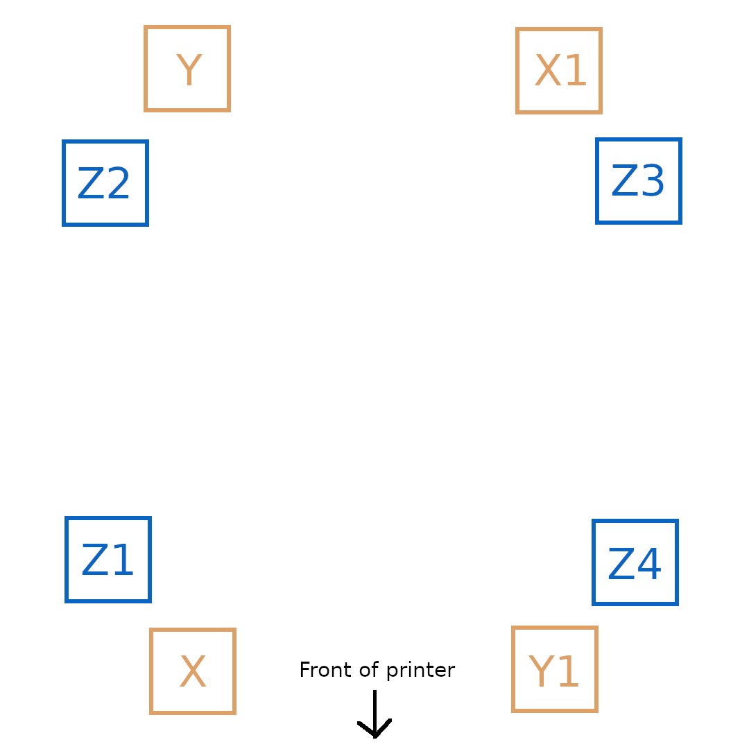
Figure 12: Motor wiring overview
And the motors are connected to the following ports on a Spider v1.0 controller board:
Motor X  - Controller X
Motor Y  - Controller Y
Motor X1 - Controller Z1
Motor Y1 - Controller E0
Motor Z  - Controller E1
Motor Z1 - Controller E2
Motor Z2 - Controller E3
Motor Z3 - Controller E4
If you intend to use the printed cable channels, install them now. Let’s get started with the motors, I started with Y1 and Z4. Strip a few inches of insulation off your multi-conductor cable. I’m using a 4-pair cable here.
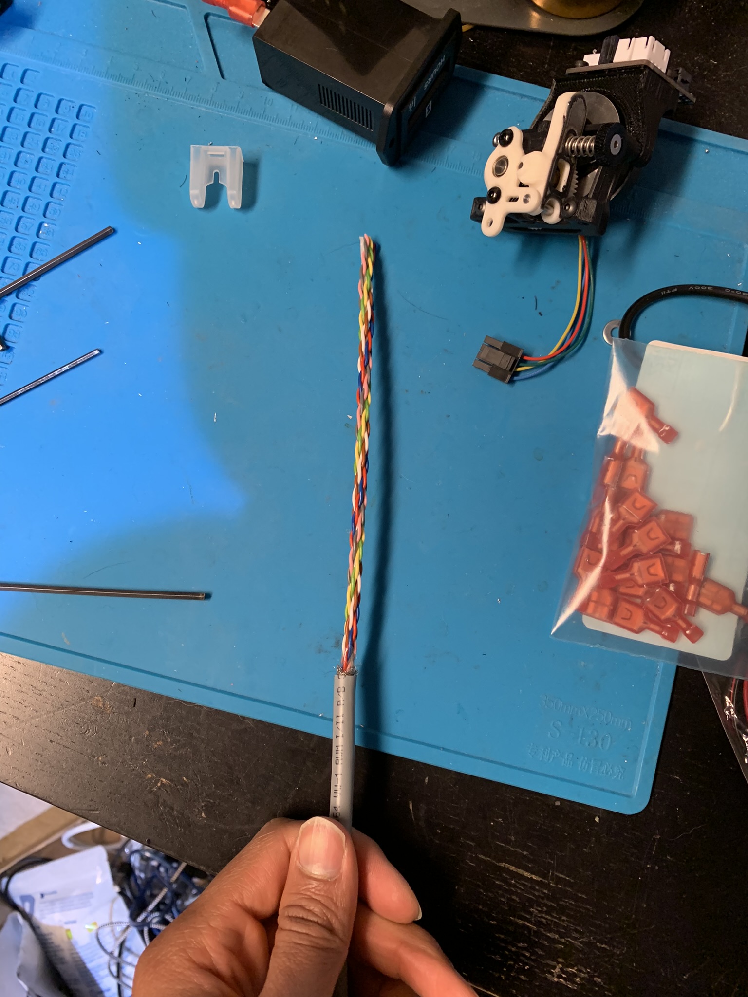
Figure 13: Multi conductor cable with a few inches of insulator
Feed it in from the front of the printer through the left grommet, and figure out how much slack you need. Crimp JST connectors on to four wires and insert them into a connector, keeping cables from a pair adjacent to each other. Plug the connector into the E0 port of your Spider v1.0 (or whatever the correct port is for your controller).
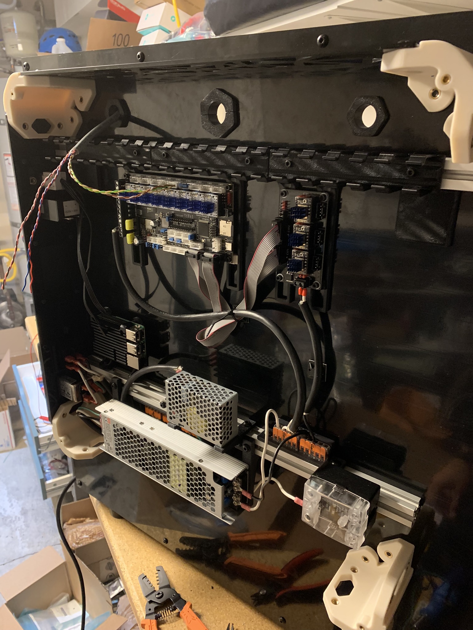
Figure 14: Wires plugged into E0 of Spider v1.0 controller
The remaining four wires will go into a connector that plugs into E4, so position them accordingly and snip off any excess. Crimp and plug in.
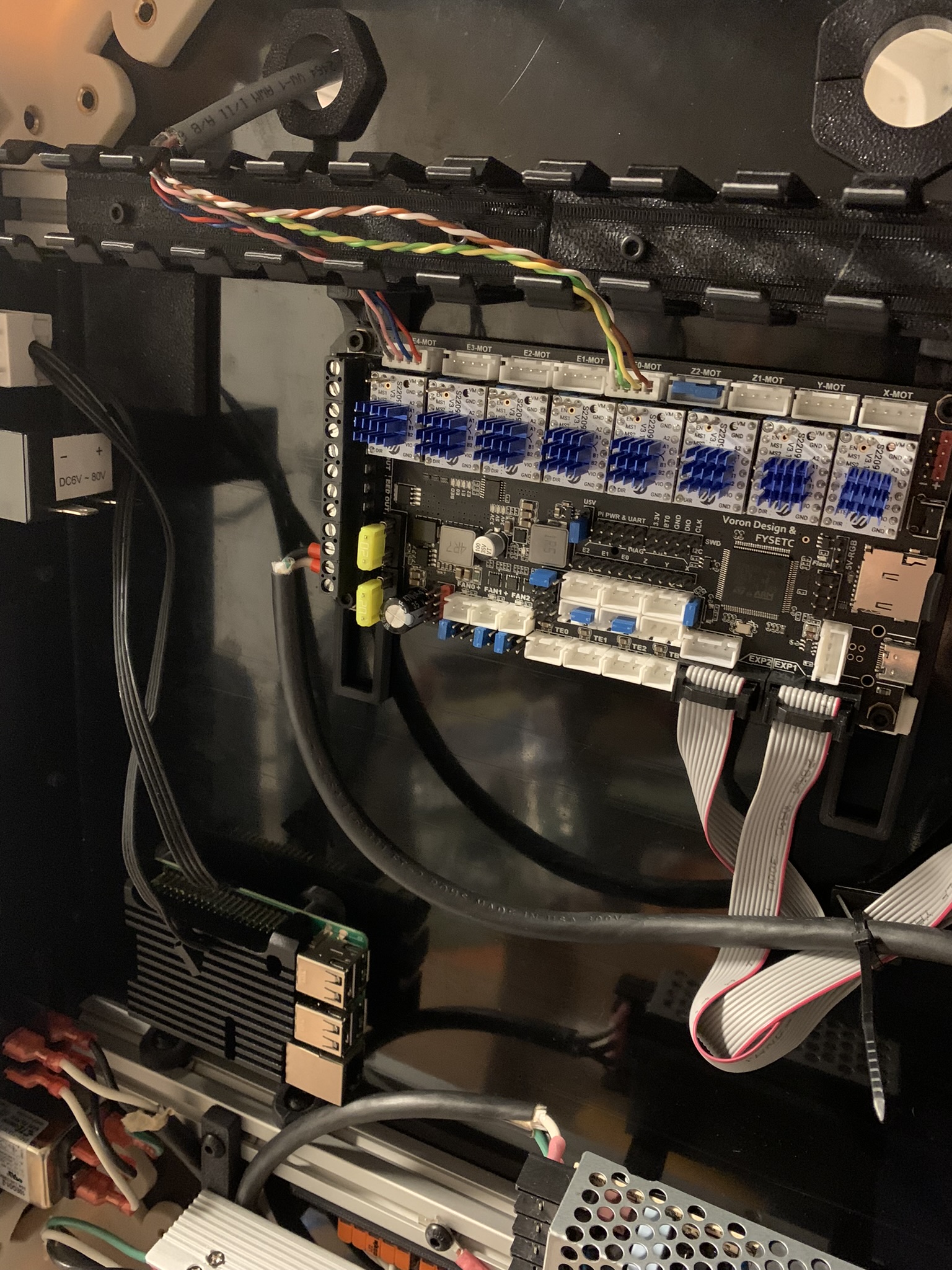
Figure 15: Wires plugged into Z3 of Spider v1.0 controller
For the other end of the cable, run it down the side vertical extrusion and through the printed cable channels next to the Z drives on the side horizontal gantry exrtusion.
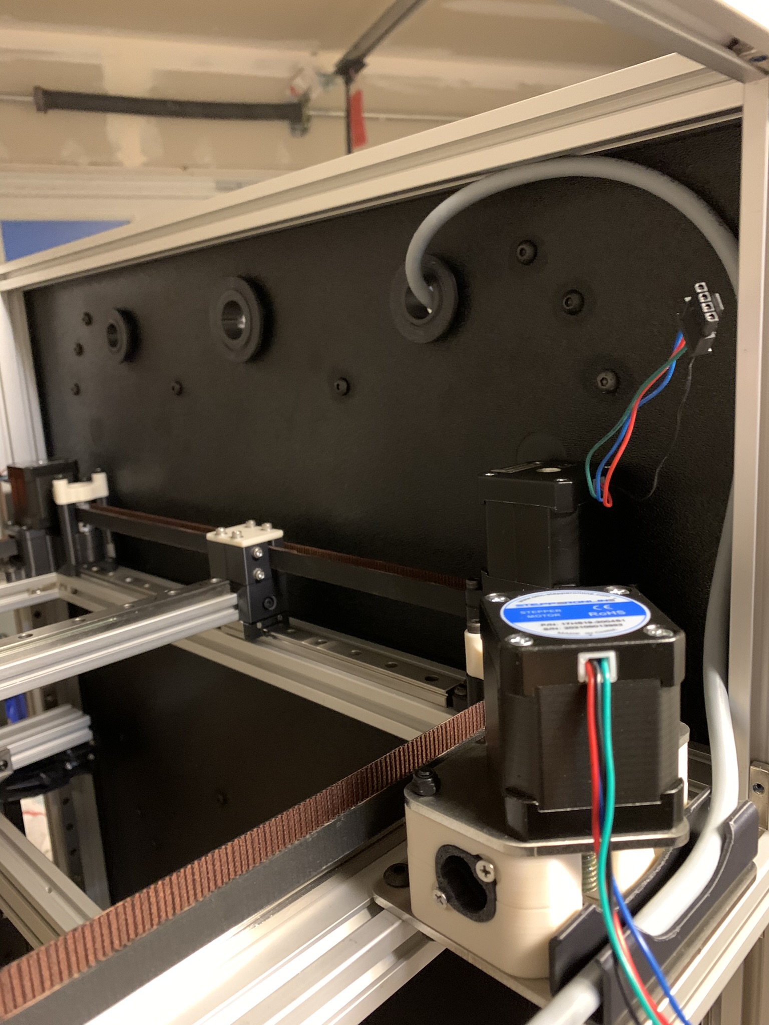
Figure 16: Cable path for Z3 and Y1 motors
Figure out how long you want it to be (I terminated mine shortly past the front right cable channel, in the front right corner of the gantry) and snip it there. Crimp all eight wires and insert four into one connector, giving you two connectors. Ensure that the Z3 wires go into one connector and the Y1 wires go into the other. Also ensure that the order of the wires matches at both connectors: Microfit 3 and JST. For example, if you have the wires plugged into Z3 on your controller in the order Red-Blue-White-Brown, ensure that you insert them in the same order into your Microfit connector.
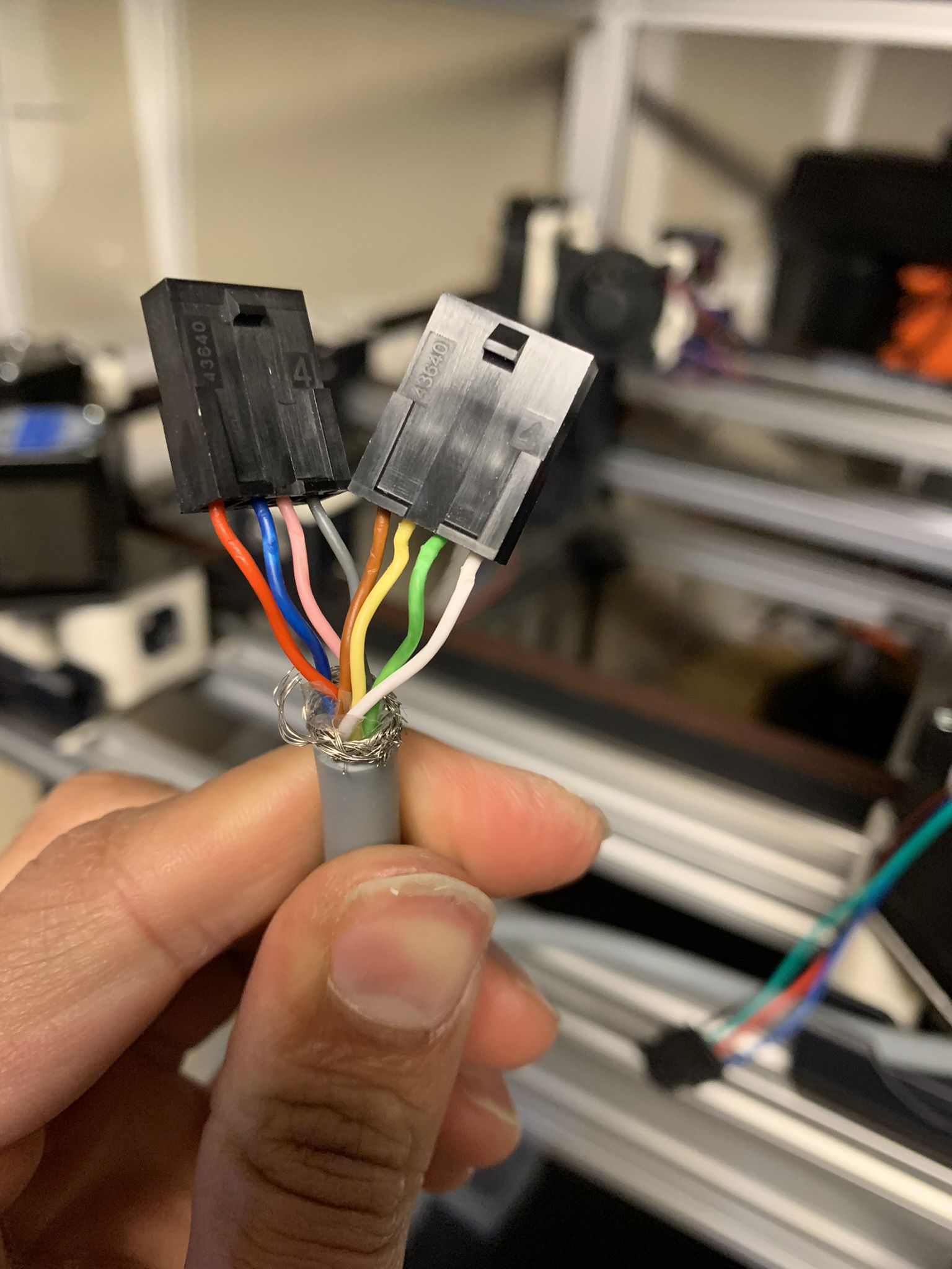
Figure 17: 4 pair cable with connectors
Now, snip your Y1 and Z3 motor wires to an appropriate length so that they’ll plug into the connectors you just made with a minimum of slack. Crimp them and add mating connectors.
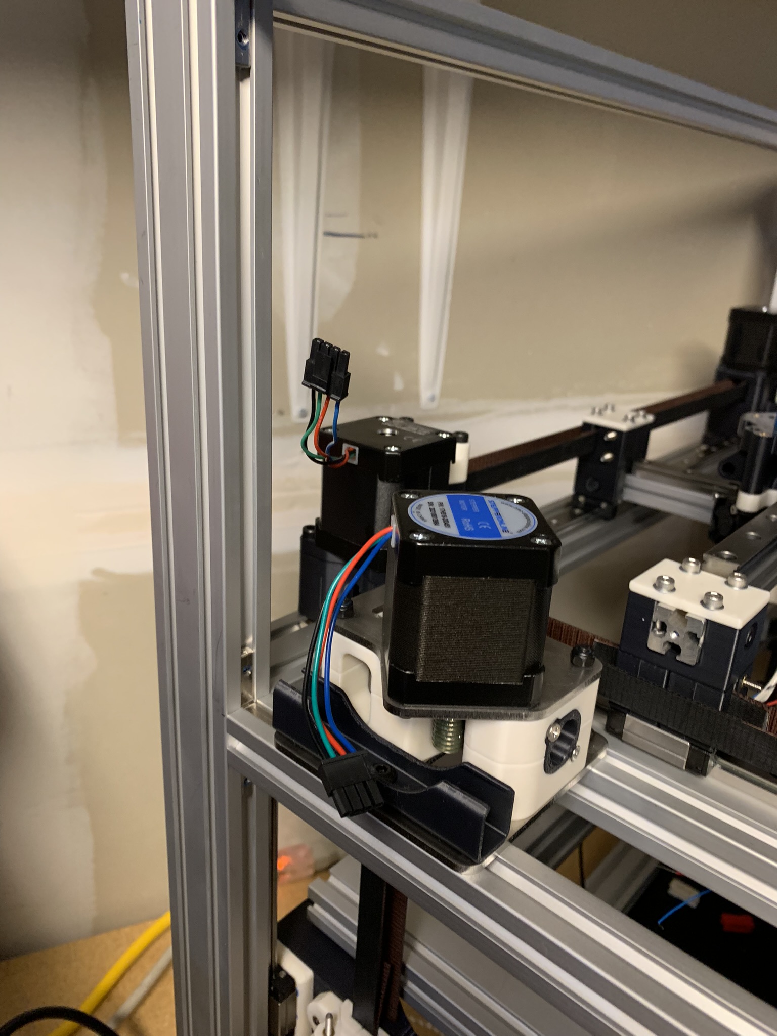
Figure 18: Y1 and Z3 motor wires with connectors
Plug in the connectors, once again paying attention to which is which. I used printed cable clips to hold the wires in place.
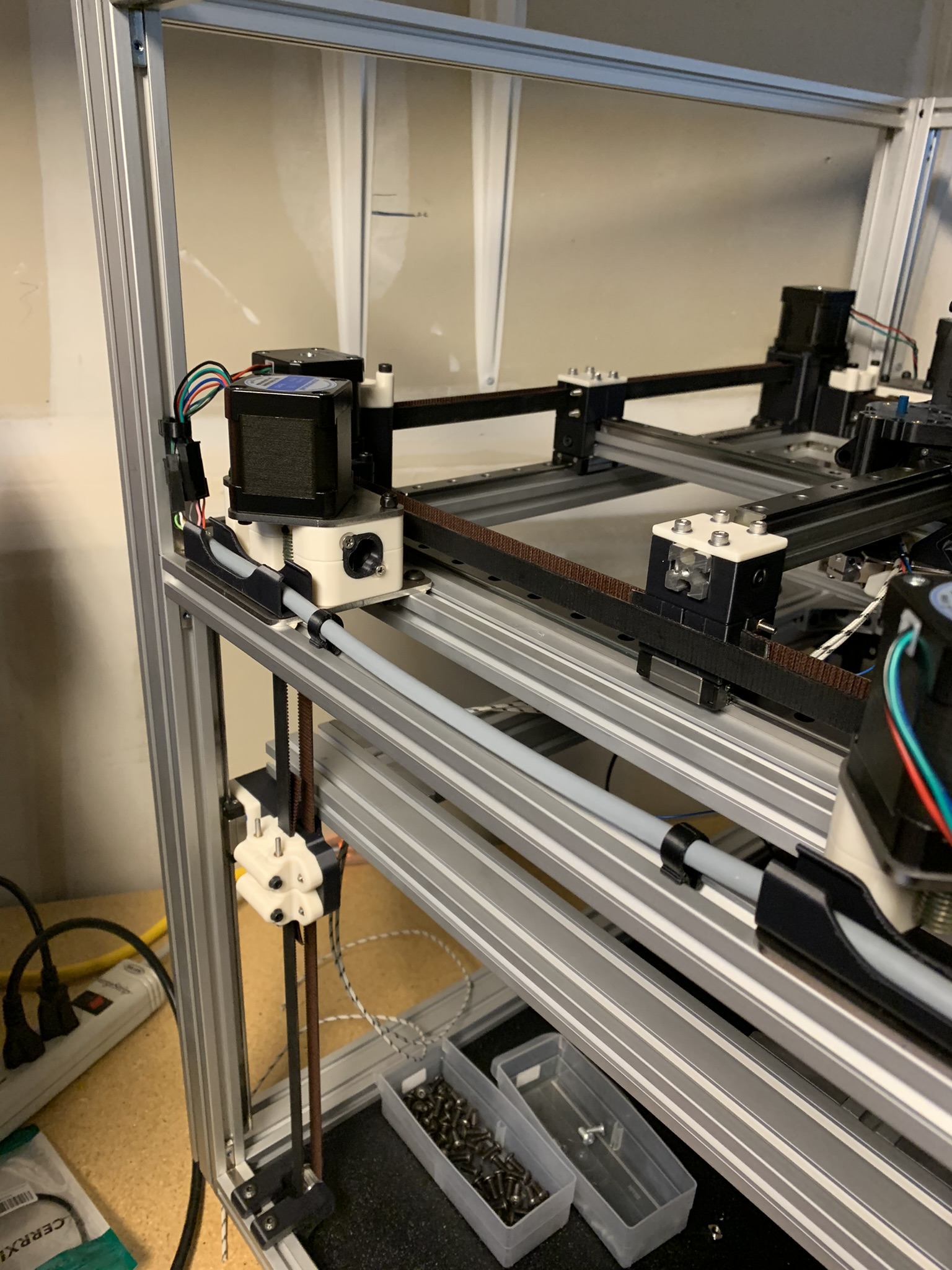
Figure 19: Y1 and Z3 motors connected and wires held in place with clips
Repeat this for the X1 and Z2 motors. Connect to Z1 and E3 on your Spider.
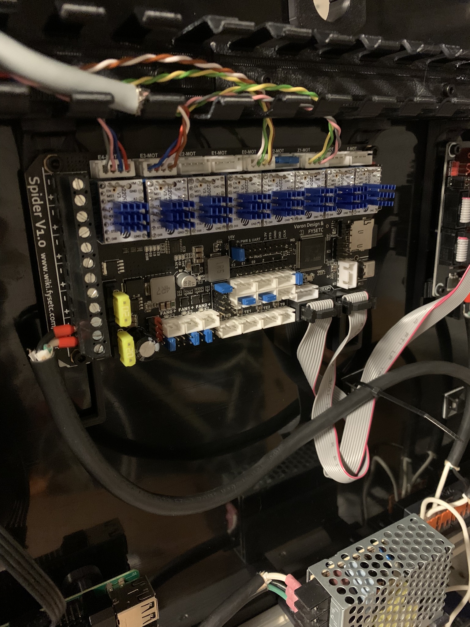
Figure 20: X1 and Z2 motor wires plugged into Z1 and E3 of Spider v1.0 controller
I terminated the 4-pair cable in the back right corner. As before, attach connectors, snip motor wires at the appropriate length and attach mating connectors, connect them.
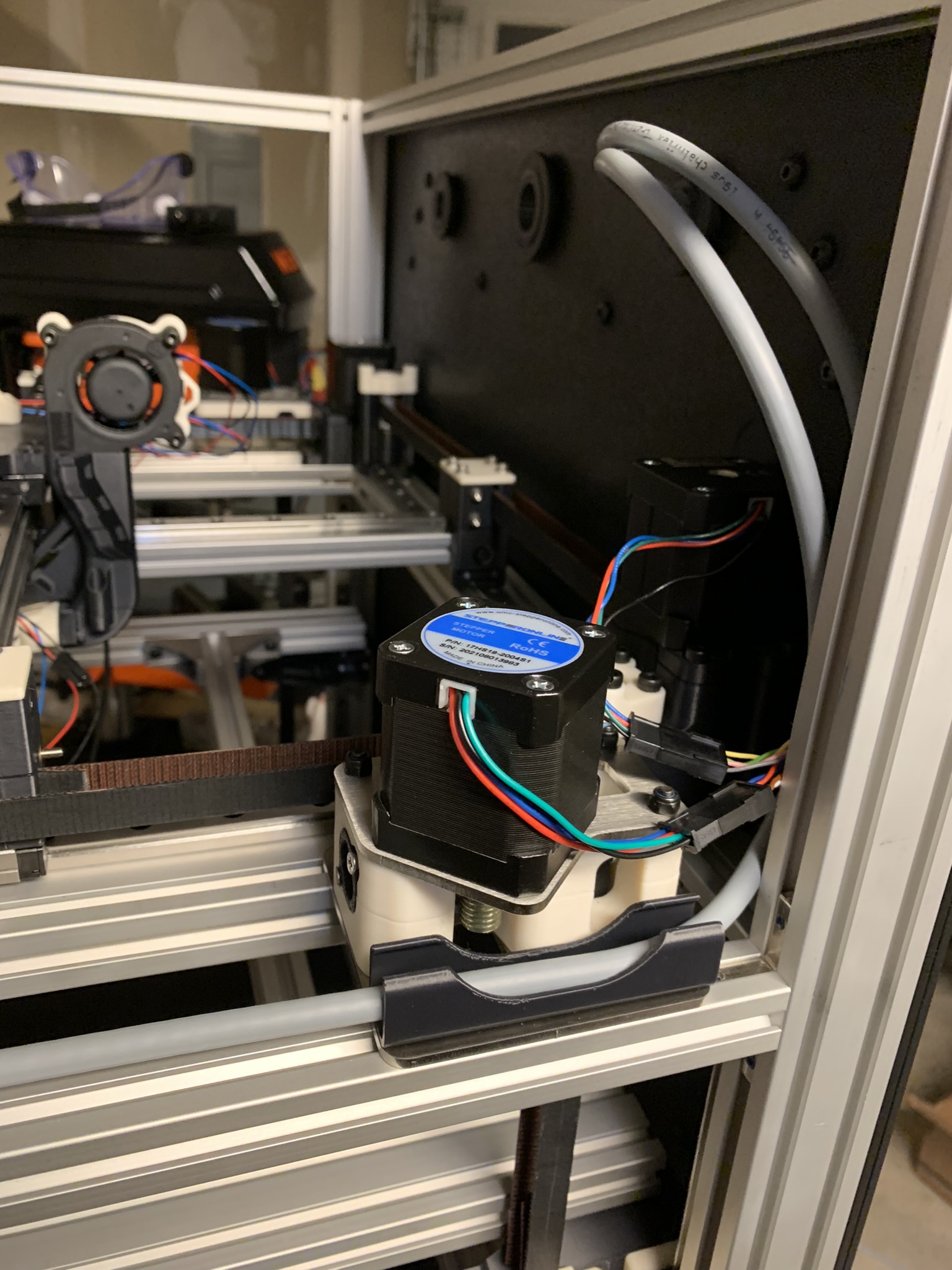
Figure 21: X1 and Z2 motor wires connected to the cable
And then use printed clips to hold them in place if desired.
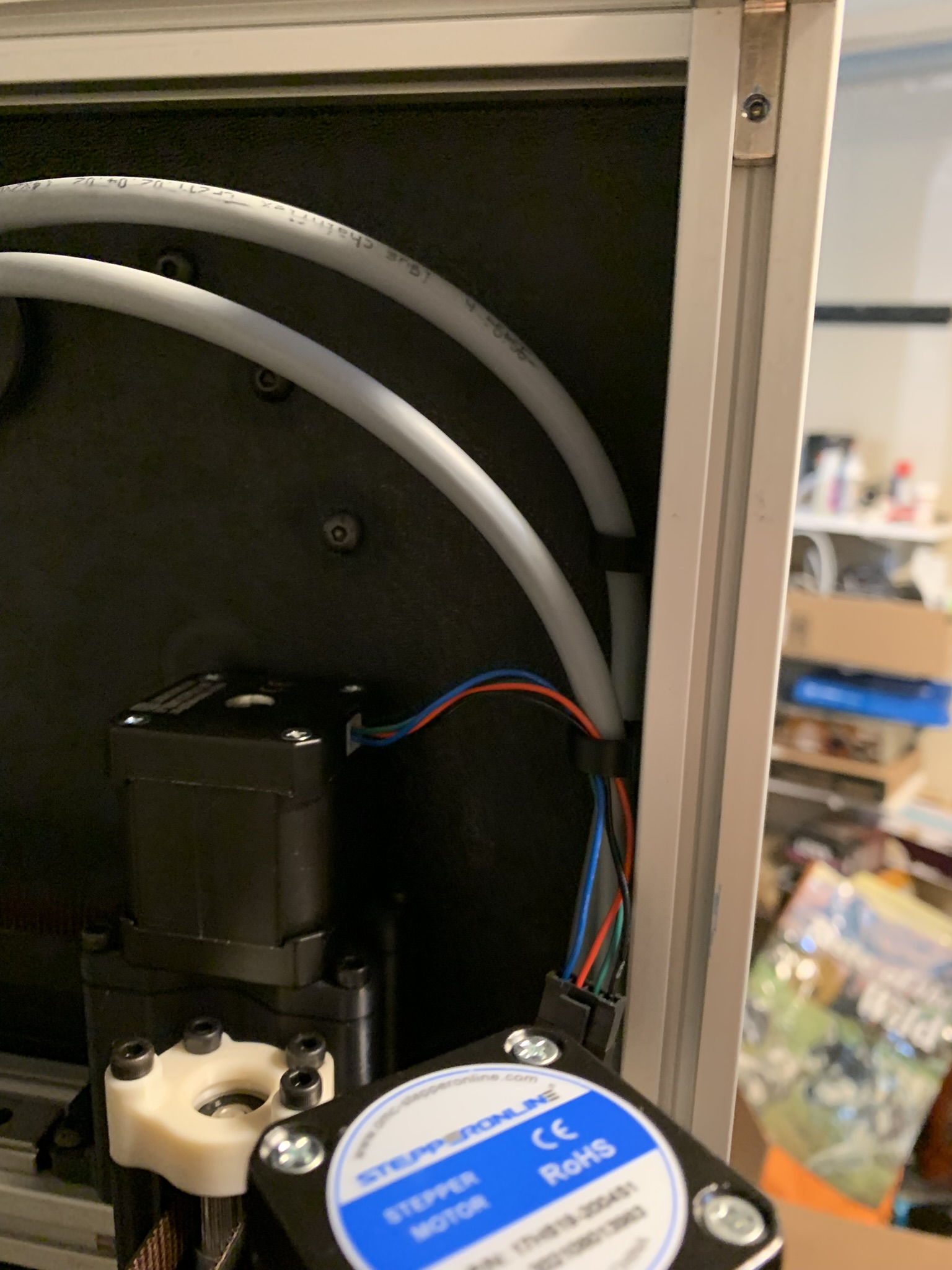
Figure 22: X1 and Z2 motor wires attached to extrusion using printed clips
Repeat the process on the front left X and Z motors, connect them to X and E1 on the controller:
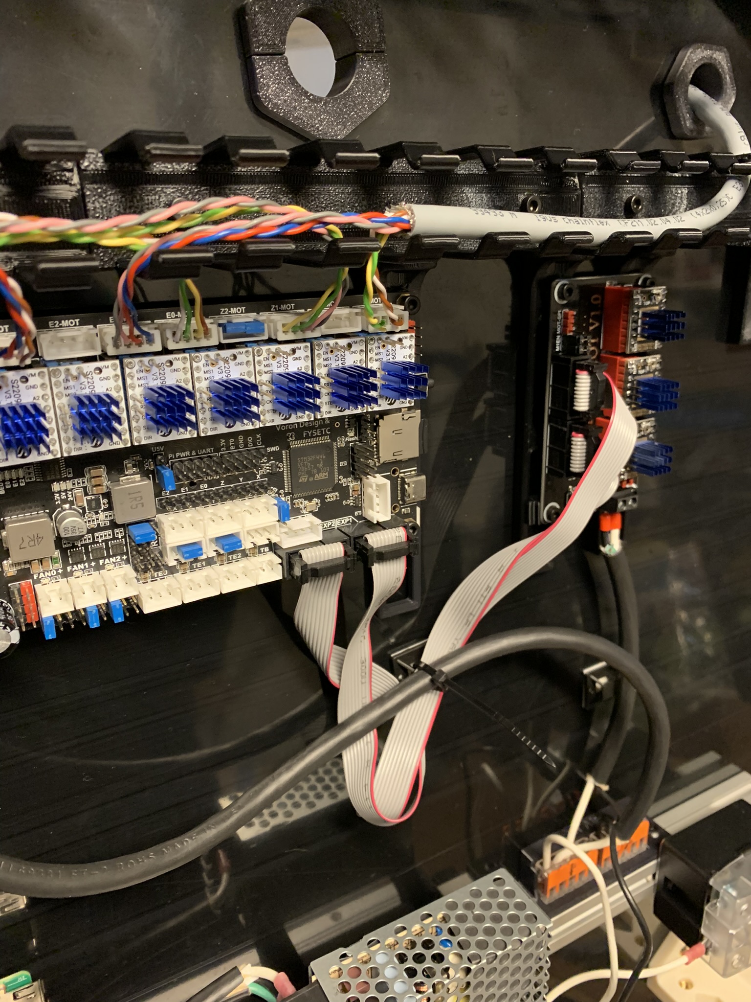
Figure 23: X and Z motor wires plugged into X and E1 of Spider v1.0 controller
Connect the motors and use printed clips
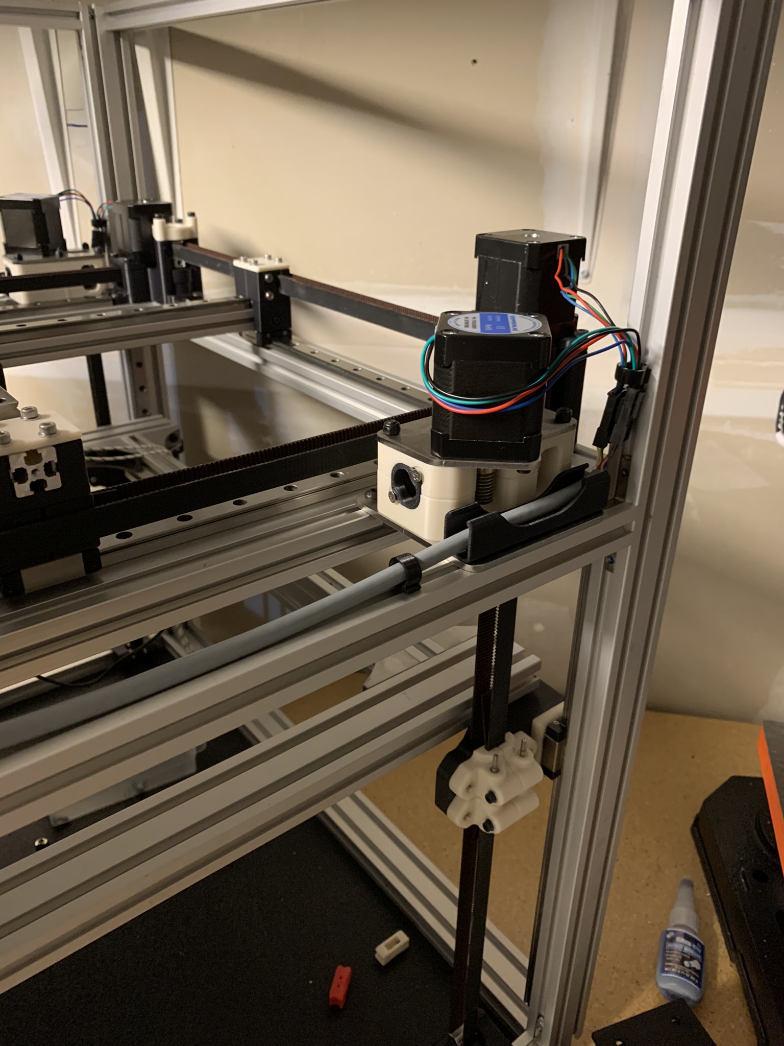
Figure 24: X and Z motor wires connected to extrusion using printed clips
And lastly, the Y and Z1 motors in the back left, connected to Y and E2 on the controller:
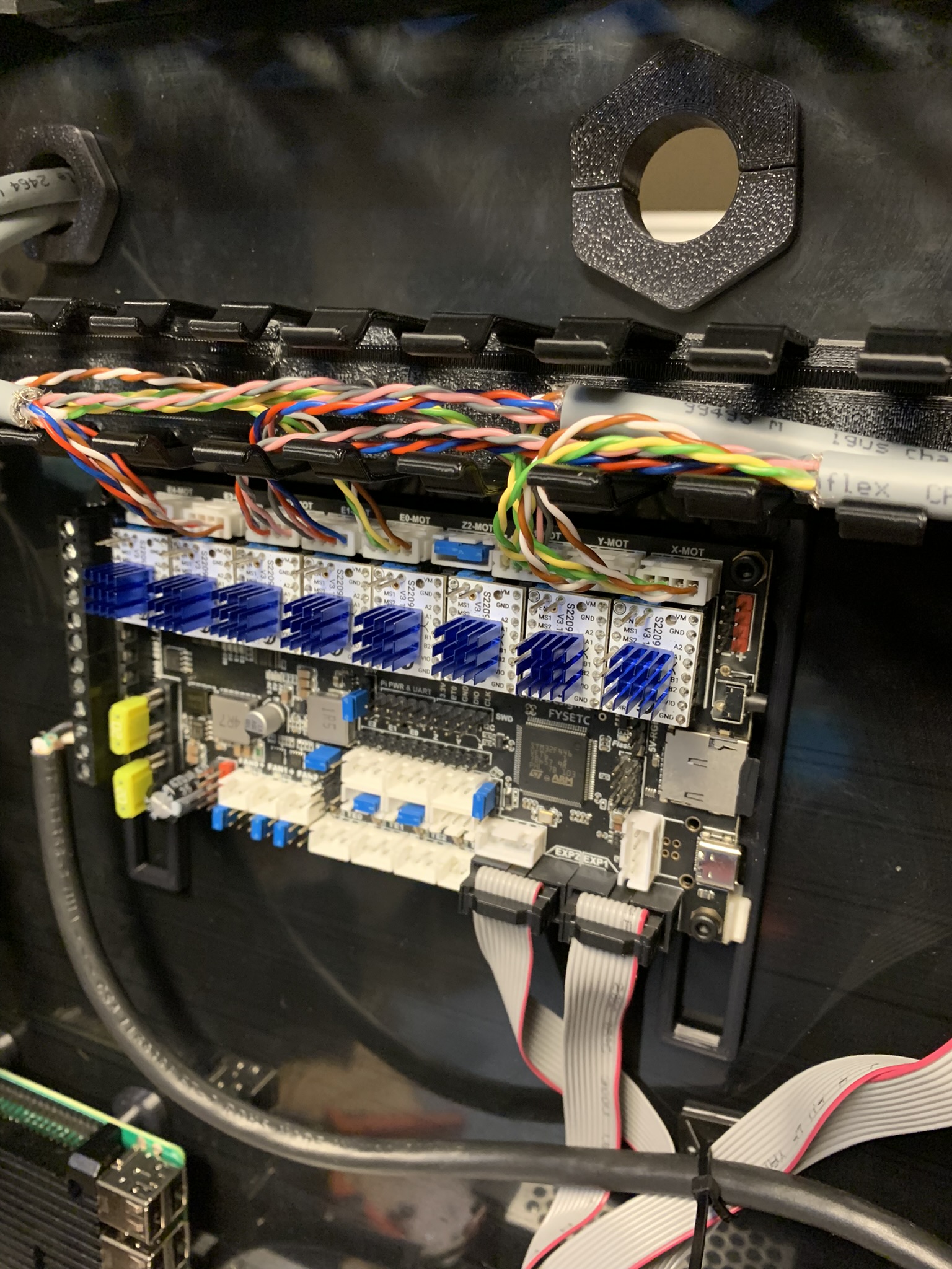
Figure 25: Y and Z1 motor wires plugged into Y and E2 of Spider v1.0 controller
Connect the motors and use printed clips.
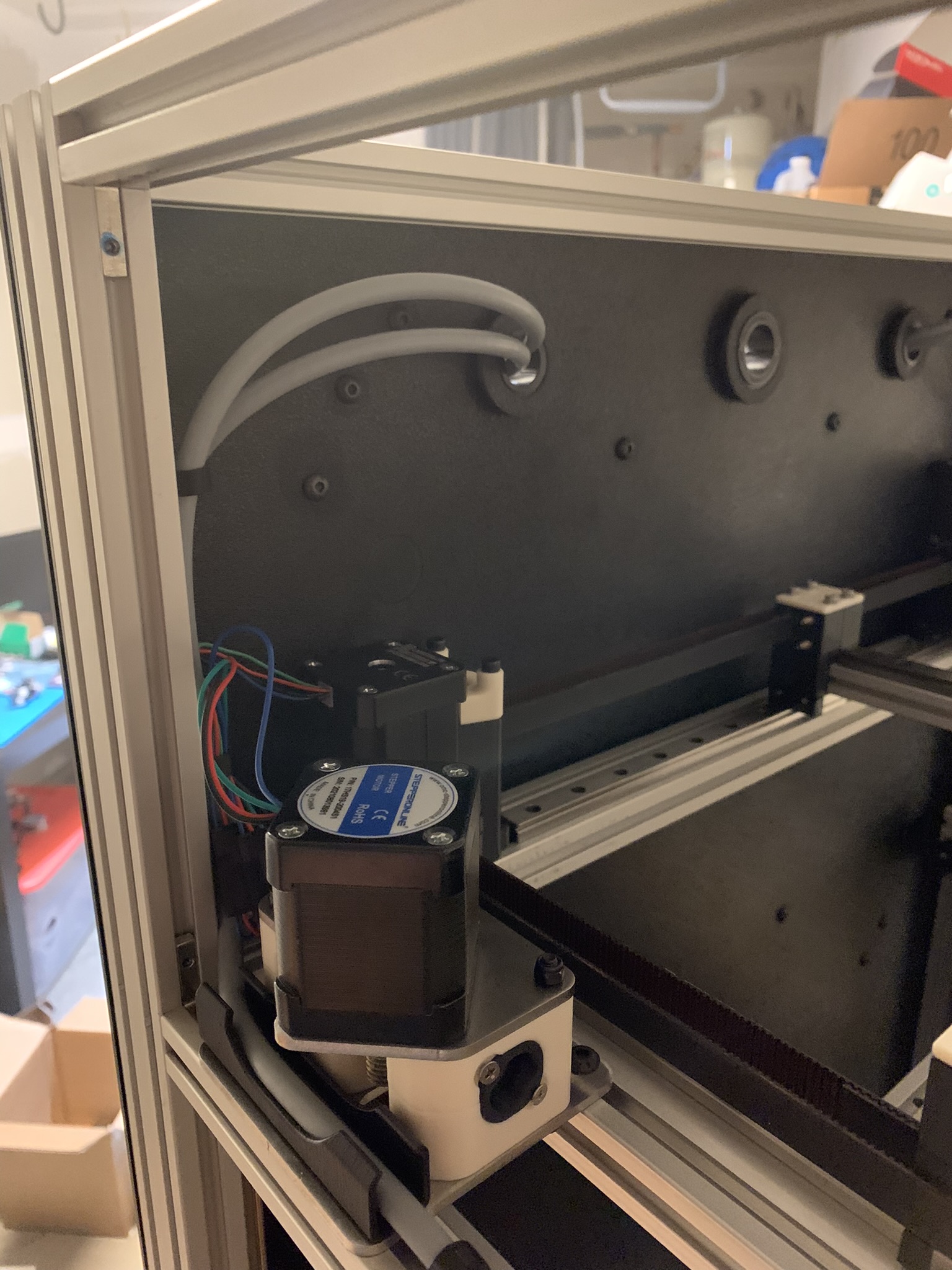
Figure 26: Y and Z1 motor wires connected to the cable
And that’s the motors all wired. Before wiring up the toolhead, we’re going to take a break to verify our wiring, and home X and Y so that we can fasten the bolts attaching the toolhead carriage to the cross rail carriages. We’ll get to that in the next part of the build log.