K2 Build Log Part Nine: Backpack
Apr 6, 2022Take a look at the eDrawing to see where everything goes inside the backpack.
Mounts
Let’s get all the mounts attached first.
UHP power supply
Insert 1x M3 tall heatset insert into each mount as shown below
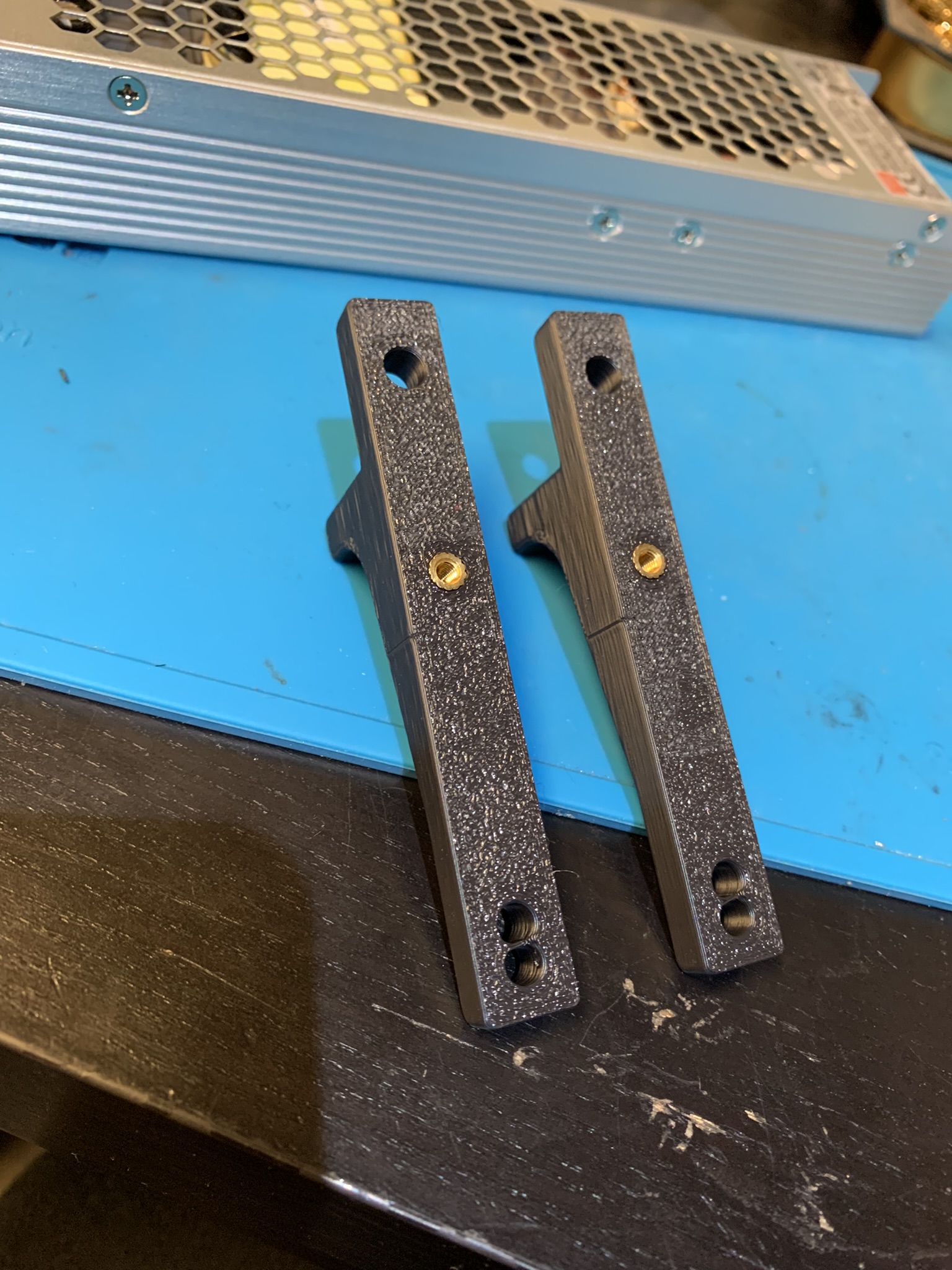
Figure 1: First heatset insert installed into uhp mounts
Hold your power supply next to a mount to figure out which of the two adjacent holes the second heatset insert needs to go into.
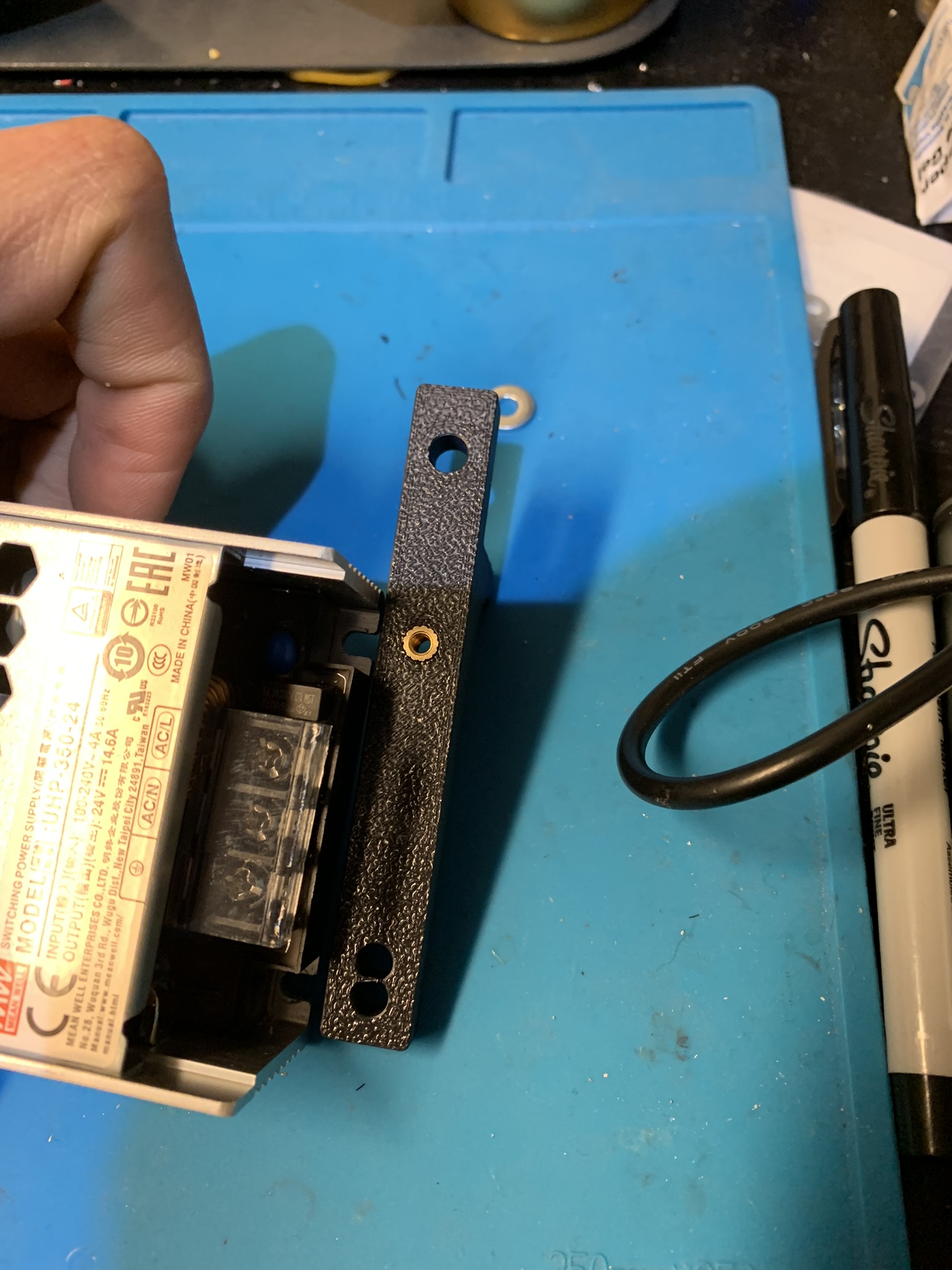
Figure 2: Figuring out hole for second uhp mount heatset insert
Put the heatset insert into the correct second hole.
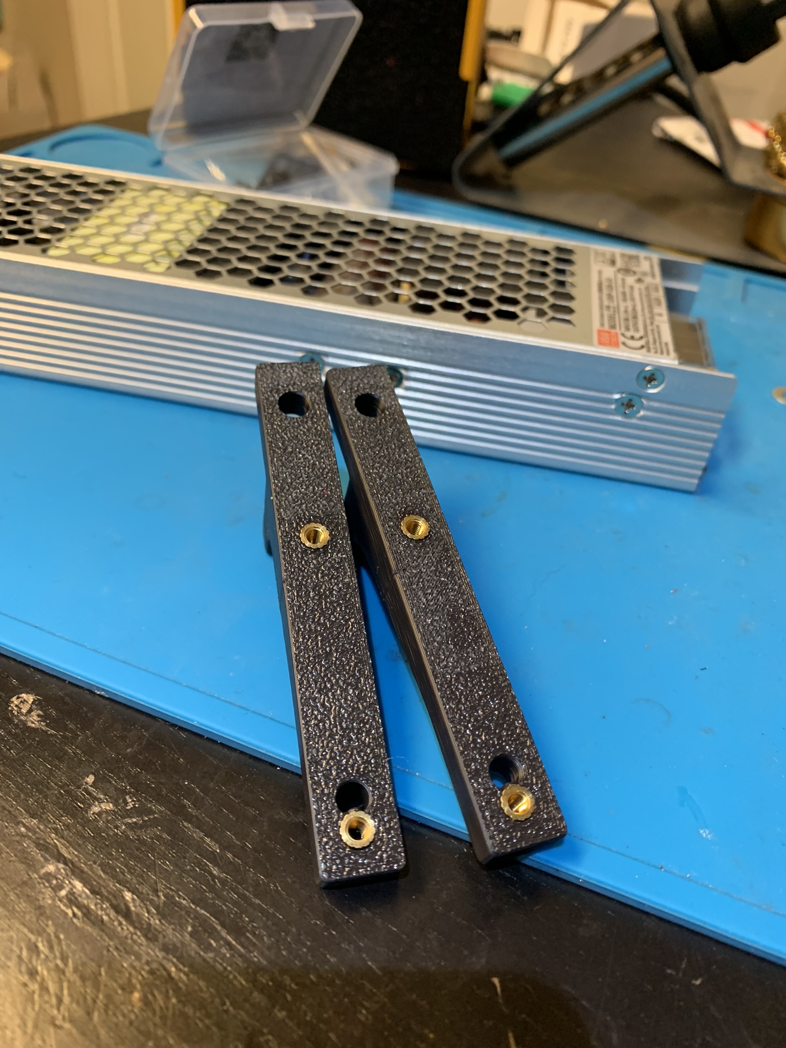
Figure 3: Second heatset insert installed into uhp mount
Use 4x M3x10 SHCS to attach both mounts to the power supply. Mind the orientation of the power supply, I oriented mine such that the input was on the left and output on the right with mounts pointing up. I originally had it oriented with the input on the right and fixed it later, so don’t get confused if the orientation looks different in later pictures.
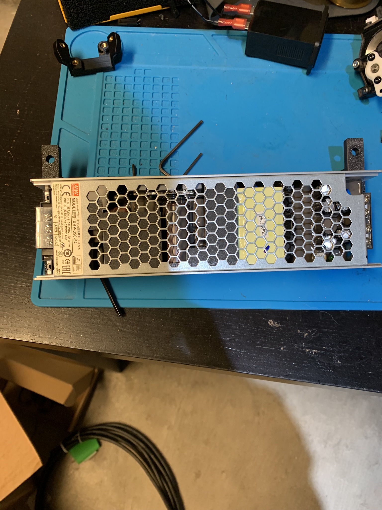
Figure 4: Mounts attached to the power supply
Bolt the mounts to a backpack extrusion using 2x M5x10 BHCS on the top
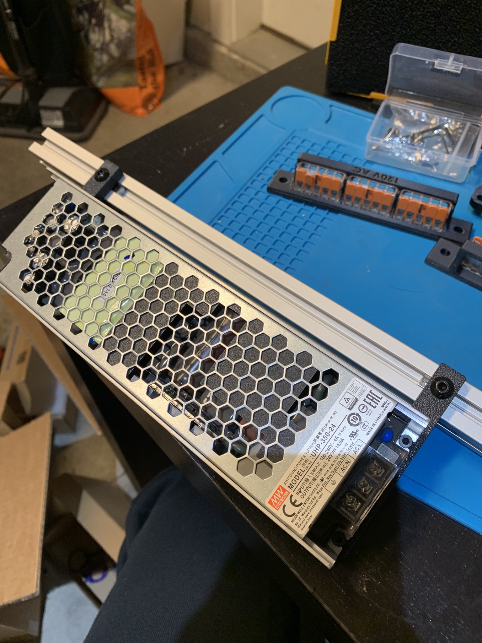
Figure 5: Mounts attached to the extrusion at the top
and two on the side
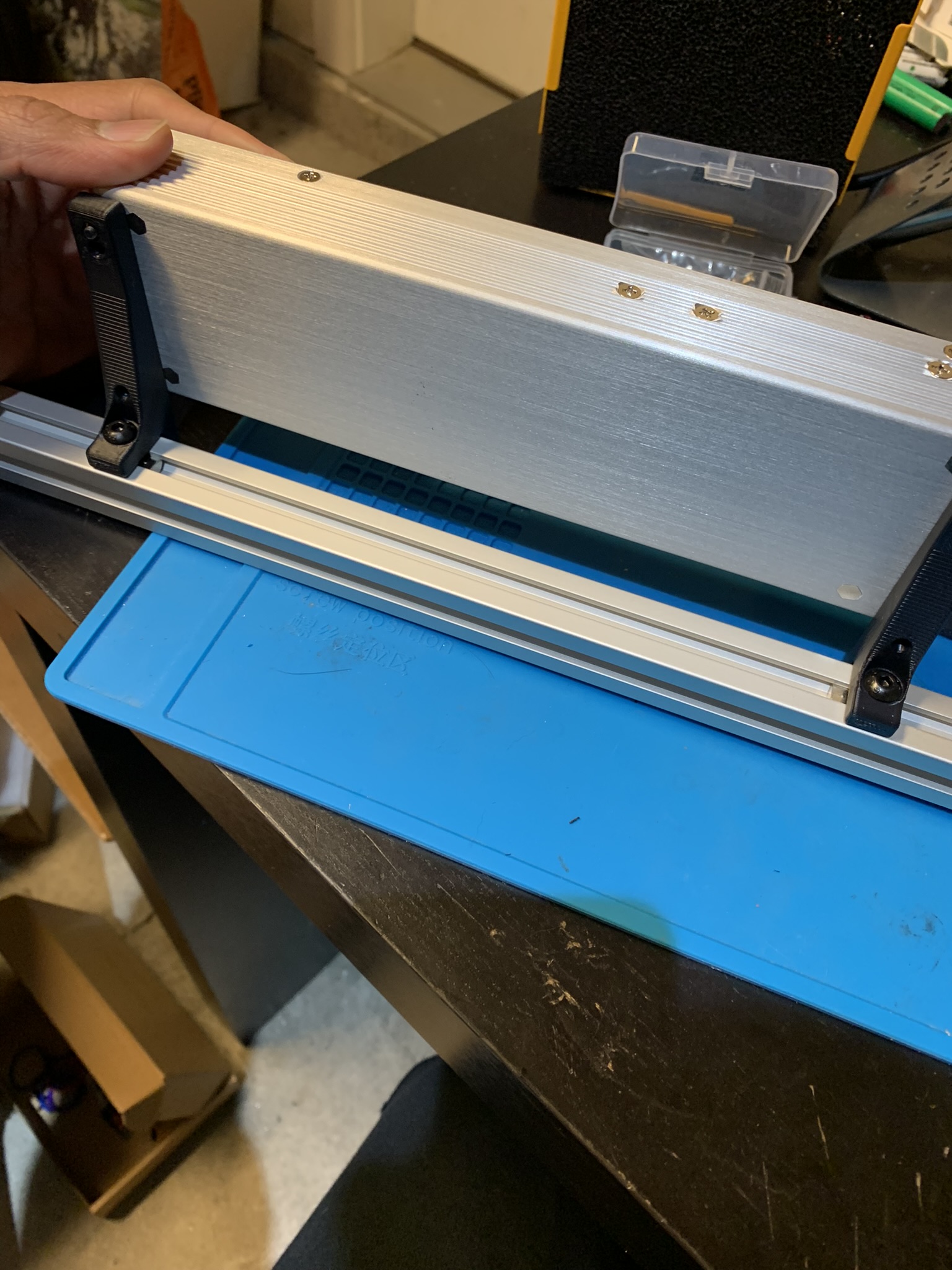
Figure 6: Mounts attached to the extrusion at the side
RS power supply
Attach the mounts to the power supply using 2x M3x8 SHCS.
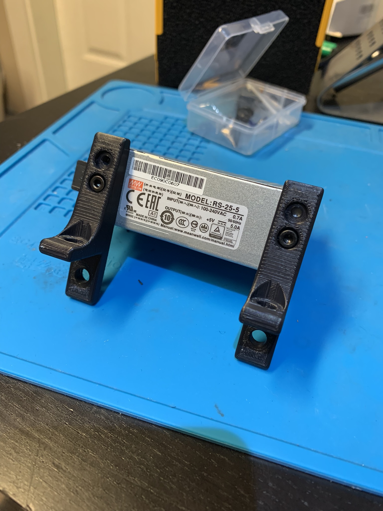
Figure 7: Mounts attached to RS power supply
Attach the mounts to the extrusion using 2x M5x10 BHCS on the top
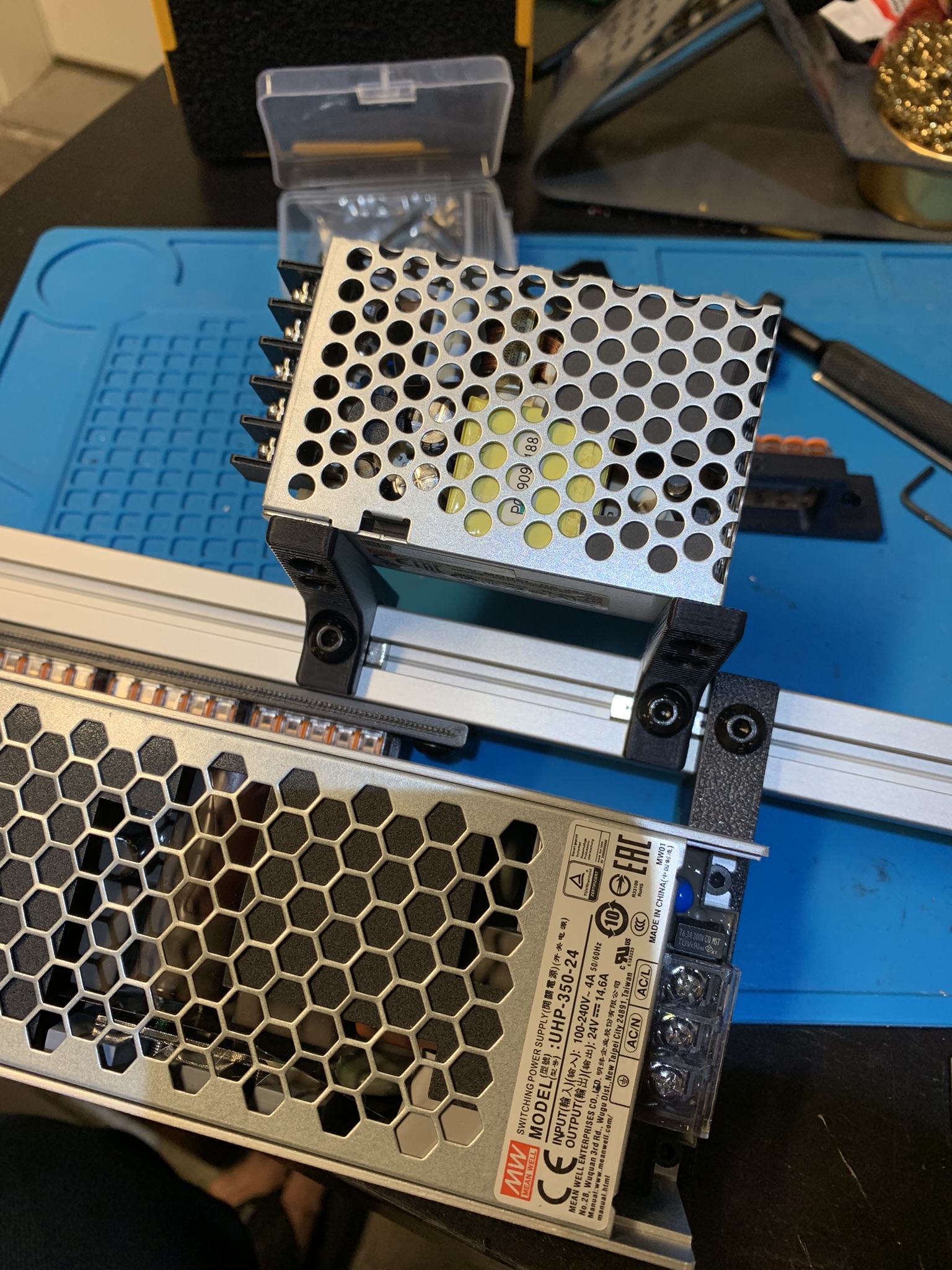
Figure 8: Mounts attached to the extrusion at the top
and two on the side
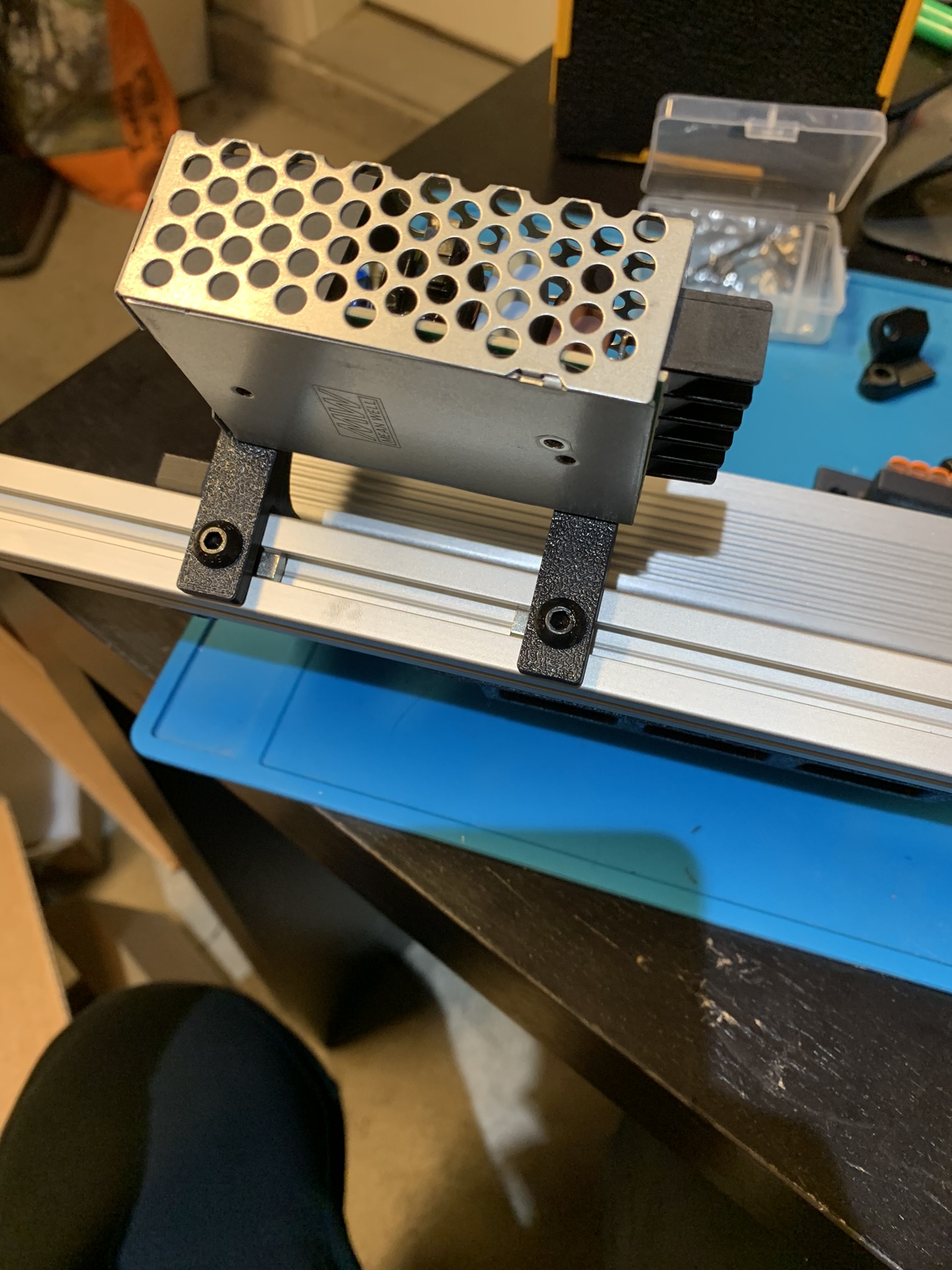
Figure 9: Mounts attached to the extrusion at the side
SSR
Attach the SSR to the extrusion using 2x M3x8 SHCS. Mind the orientation.
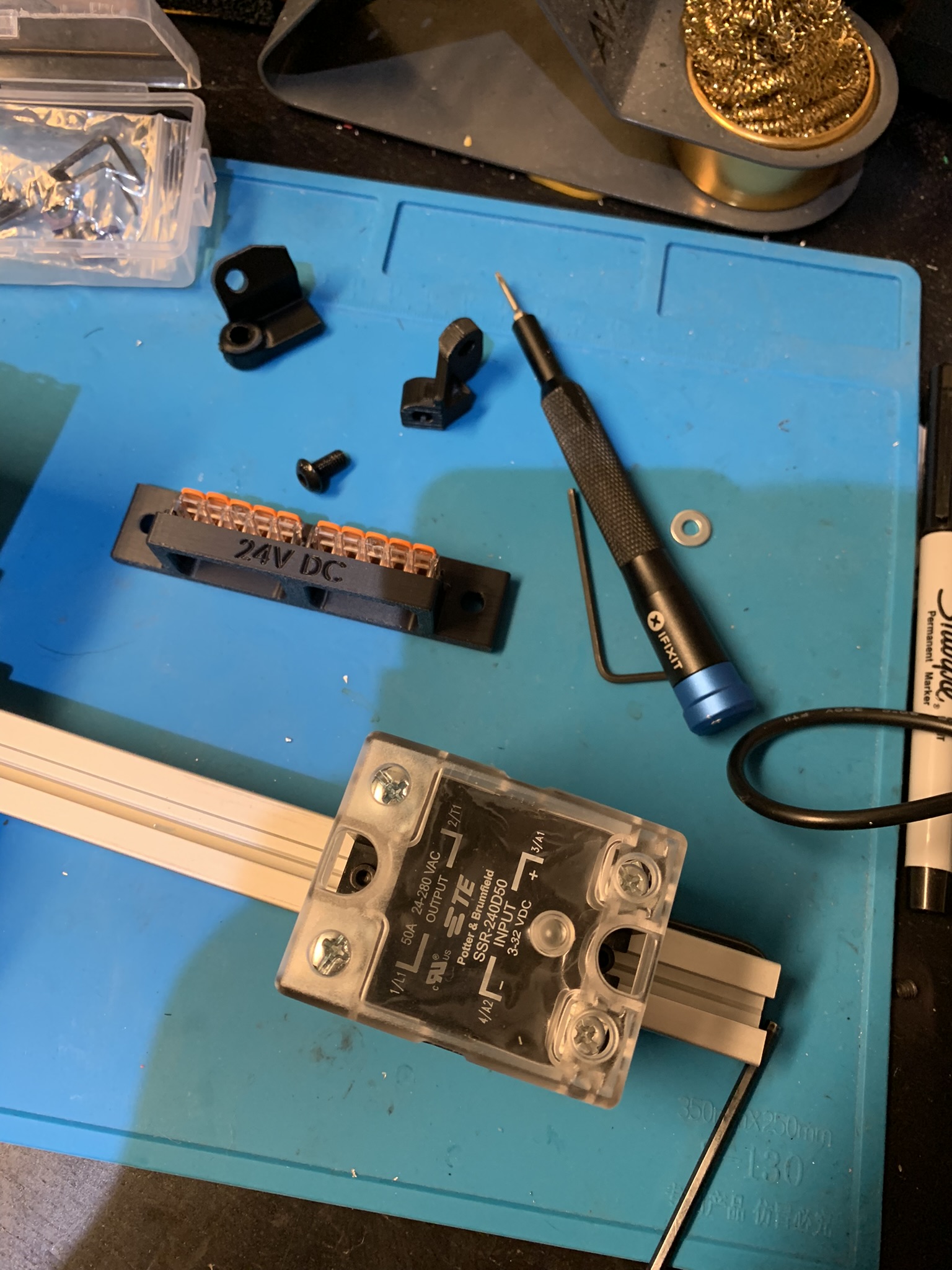
Figure 10: SSR attached to the extrusion
WAGOs
Let’s prepare the WAGO mounts. Place the WAGO mount in place
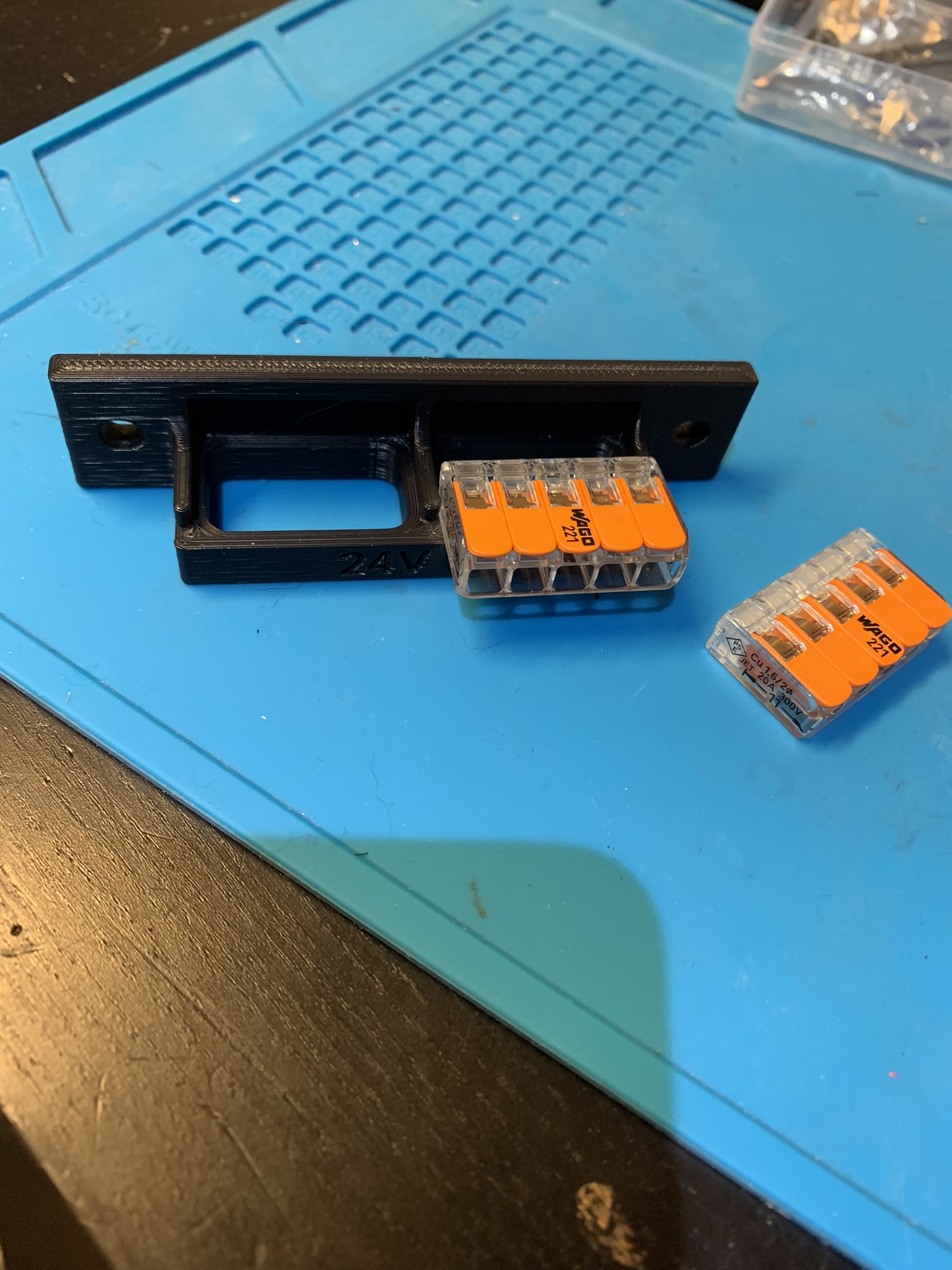
Figure 11: WAGO mount placed in the slot in the 24V mount
And slide it in. It should click into place.
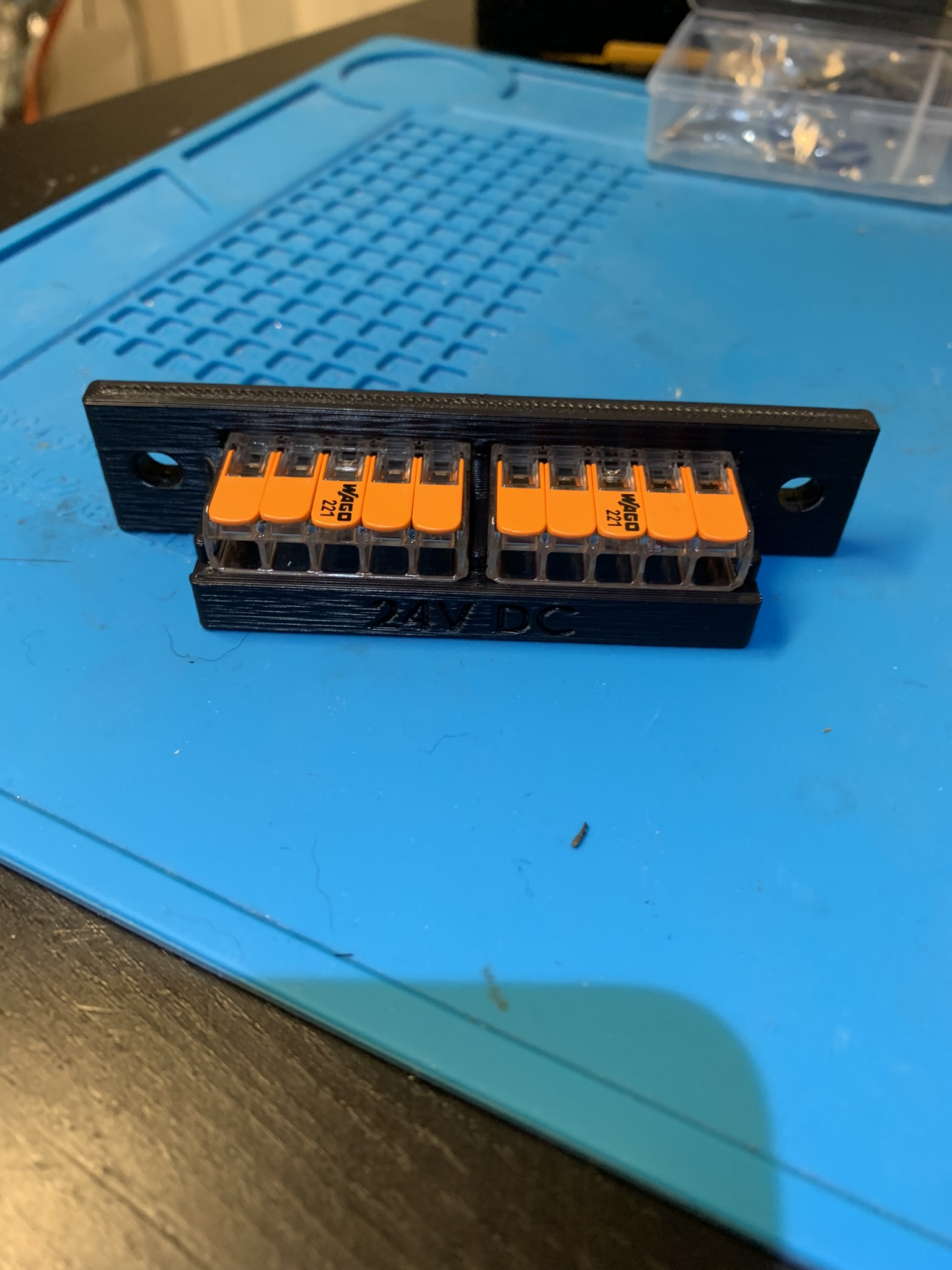
Figure 12: WAGO mounts slid into the slots in the 24V mount
Repeat for the other WAGO in this mount and the WAGOs in the other mount.
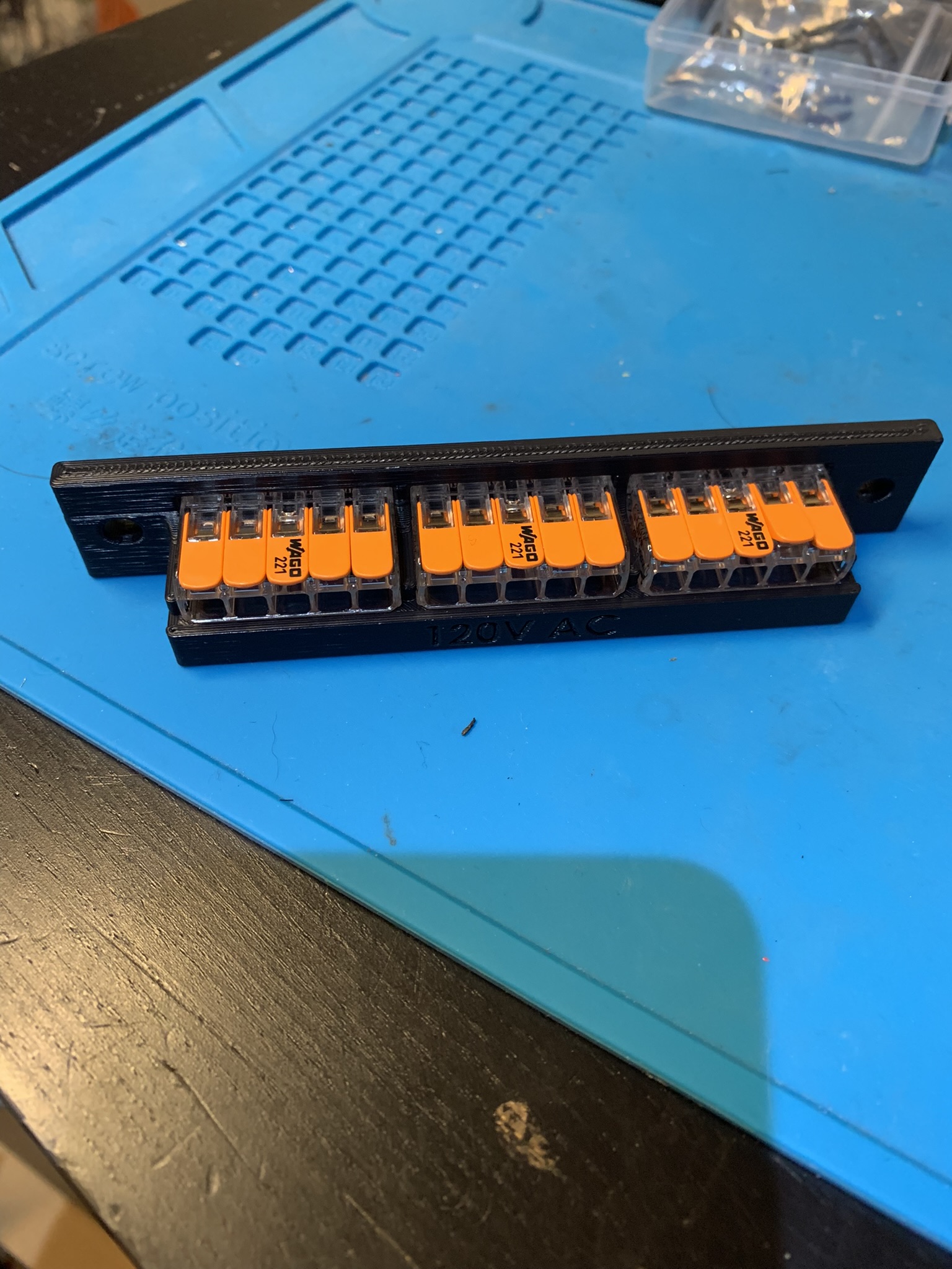
Figure 13: WAGO mounts slid into the slots in the 120V mount
Attach the 24V WAGO mount to the extrusion using 2x M5x10 BHCS.
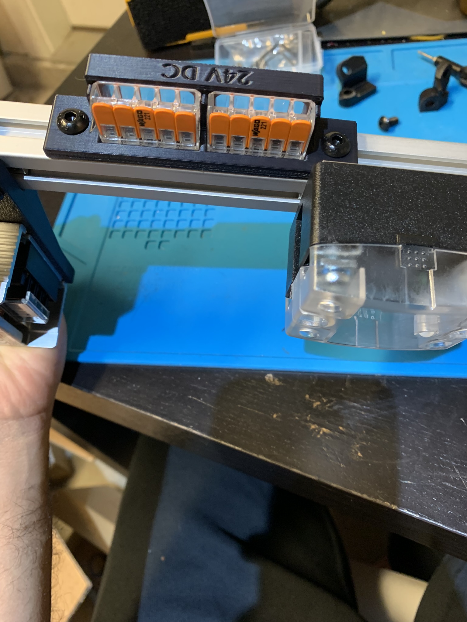
Figure 14: 24V WAGO mount attached to the extrusion
Attach the 120V WAGO mount to the extrusion using 2x M5x10 BHCS.
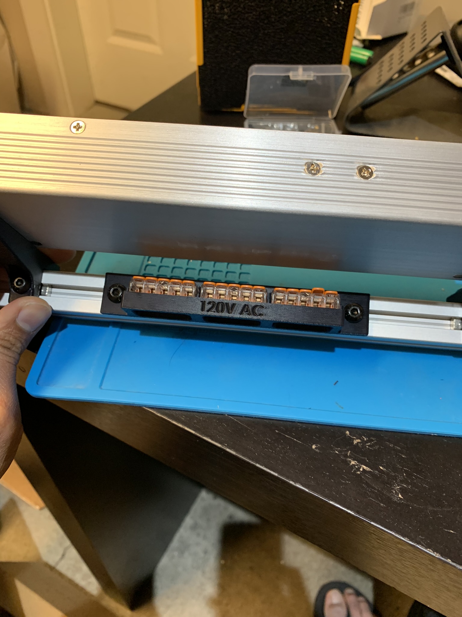
Figure 15: 120V WAGO mount attached to the extrusion
Raspberry Pi
The controller mounts are assembled identical to the Raspberry Pi mounts, so I’ll explain it here and not repeat the instructions for the other controllers.
Note - Specifically for the Pi mount, you might have to shave a bit off of the corner in the picture below. On my Raspberry Pi 3B+, that corner overlapped with one of the components soldered to the board. You’ll find out whether you need to shave yours once you’ve assembled both mounts and aligned your Pi on them.
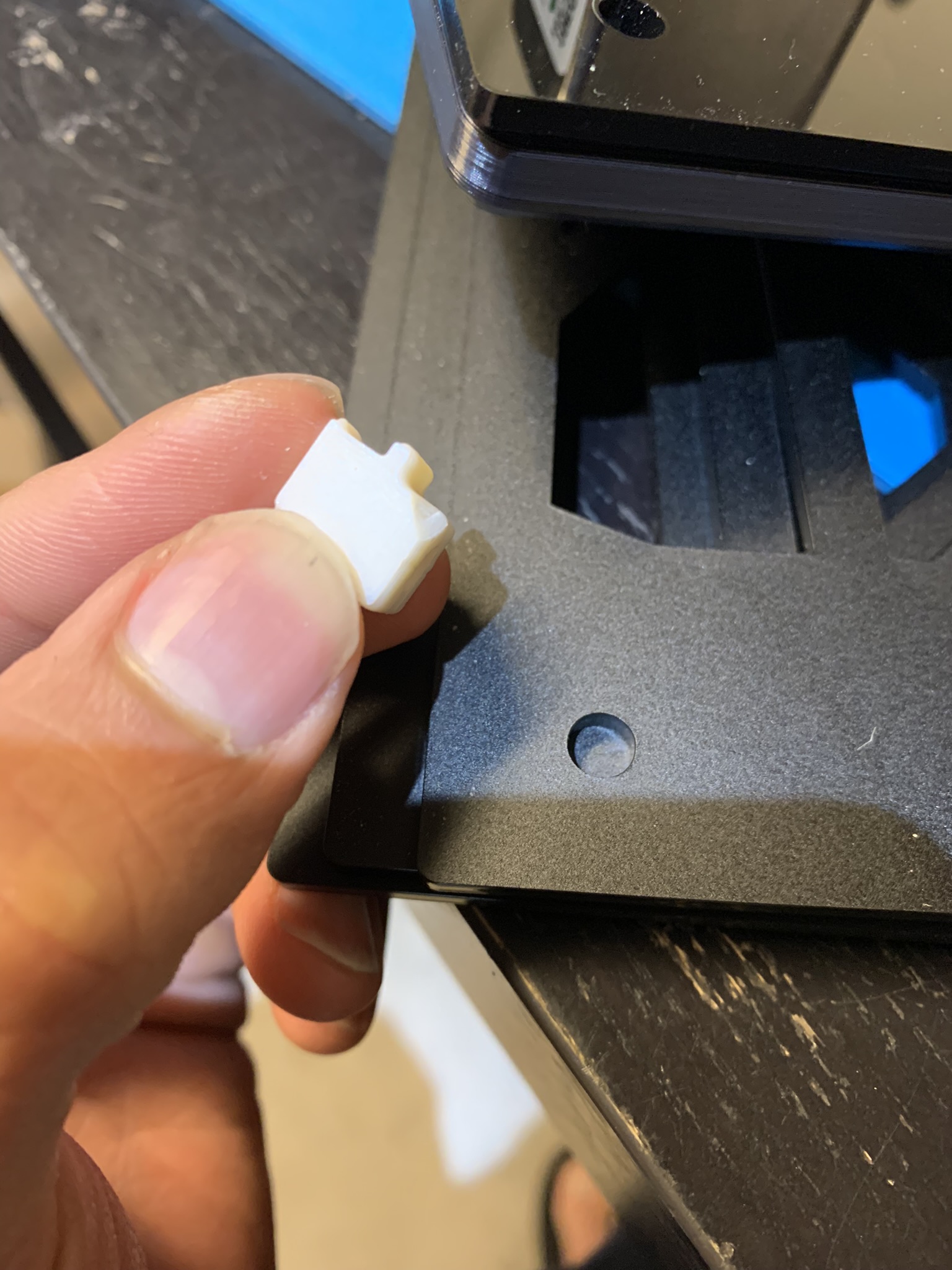
Figure 16: Corner shaved off one of the accent pieces
Place the accent pieces on the slots.
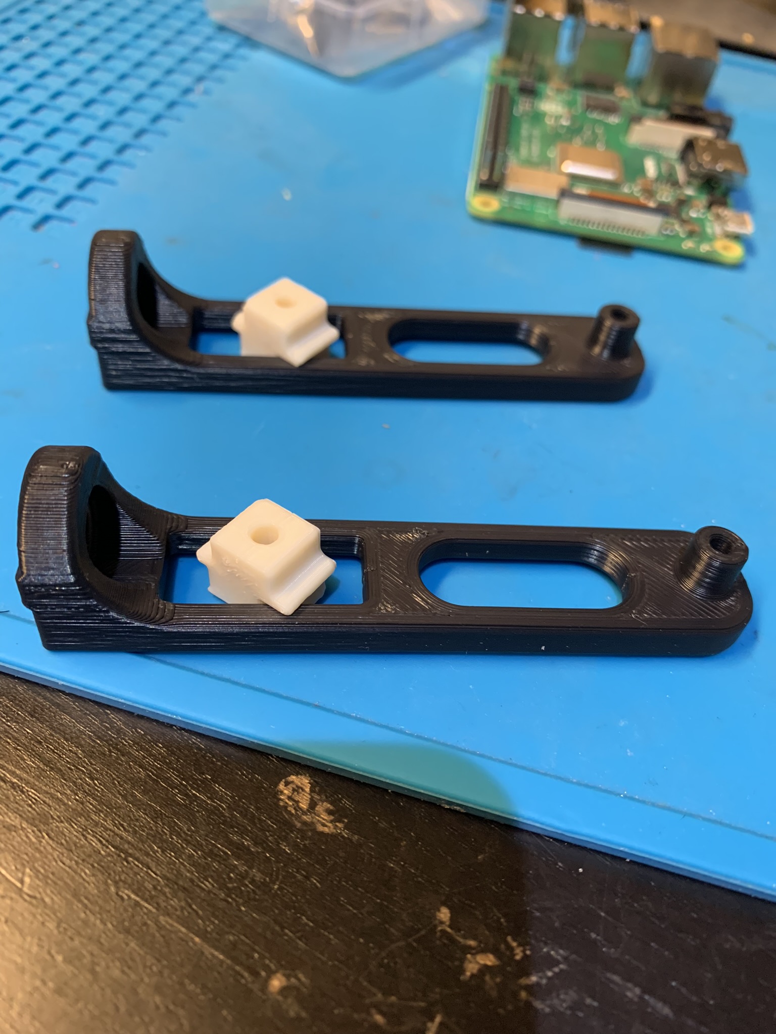
Figure 17: Mount accent pieces placed in place on the mounts
Twist the accent pieces, they’ll get locked into the slot and can be slid back and forth in the slot.
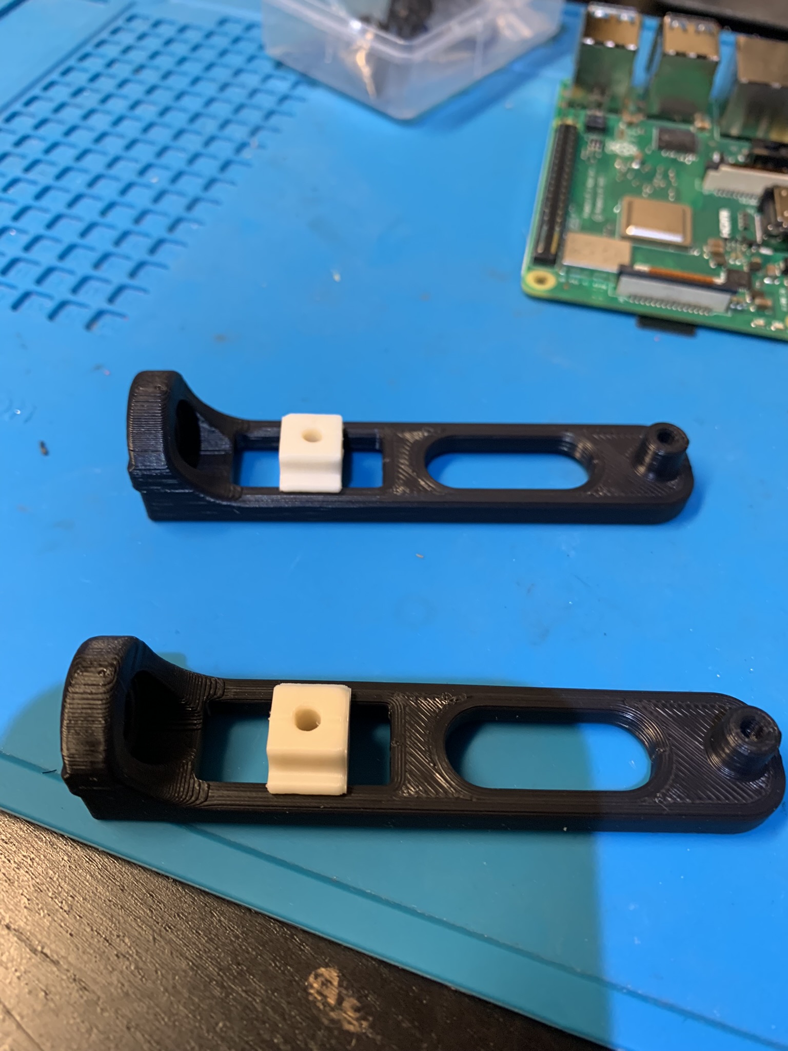
Figure 18: Mount accent pieces twisted in their slots
Place the top half of the heatsink onto the Pi, place the Pi on top of the mounts, and bolt it in using 4x M2.5x16 SHCS.
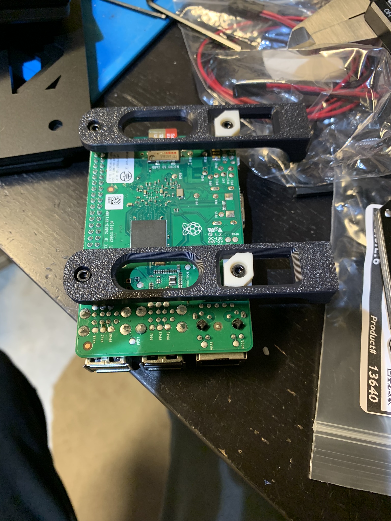
Figure 19: Pi attached to the mounts
Attach the Pi mounts to the extrusion. You’ll have to use a long hex driver and a lot of patience. I don’t have pictures of this because I attached mine after mounting the extrusion to the back panel.
Controller
Insert 2x Tall M3 inserts into the main mounts, and 2x Tall M3 inserts into the accent pieces.
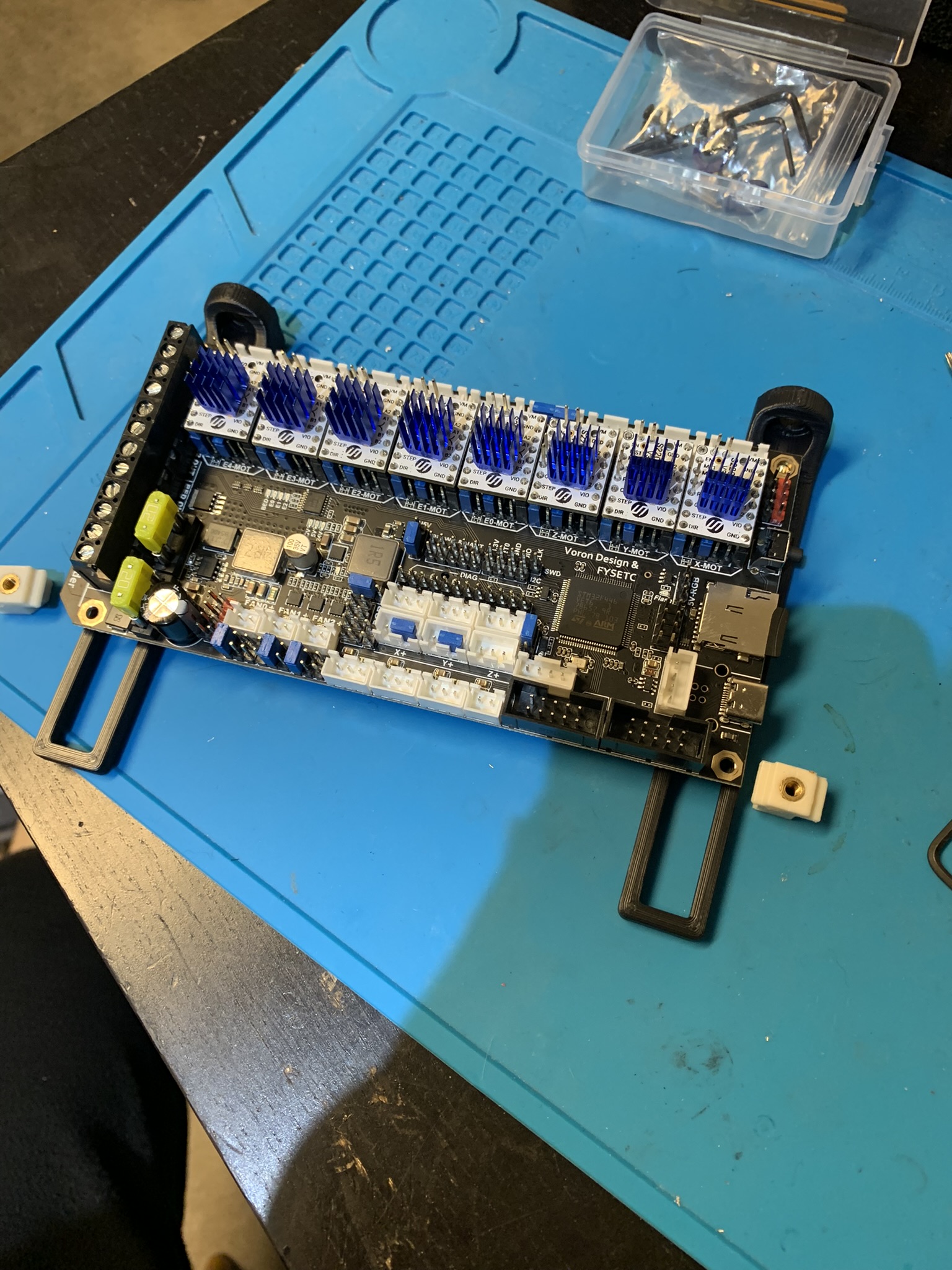
Figure 20: Heatset inserts in the controller mounts
Insert the accent pieces and twist as before.
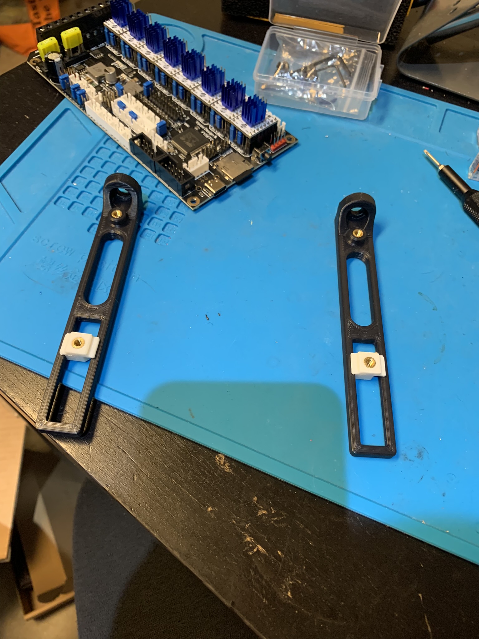
Figure 21: Accent pieces inserted into controller mounts
Slide the accent pieces to the ends of their slots and attach the controller to the accent pieces using 2x M3x8 SHCS. Attach the mounts to the extrusion using 2x M5x8 BHCS.
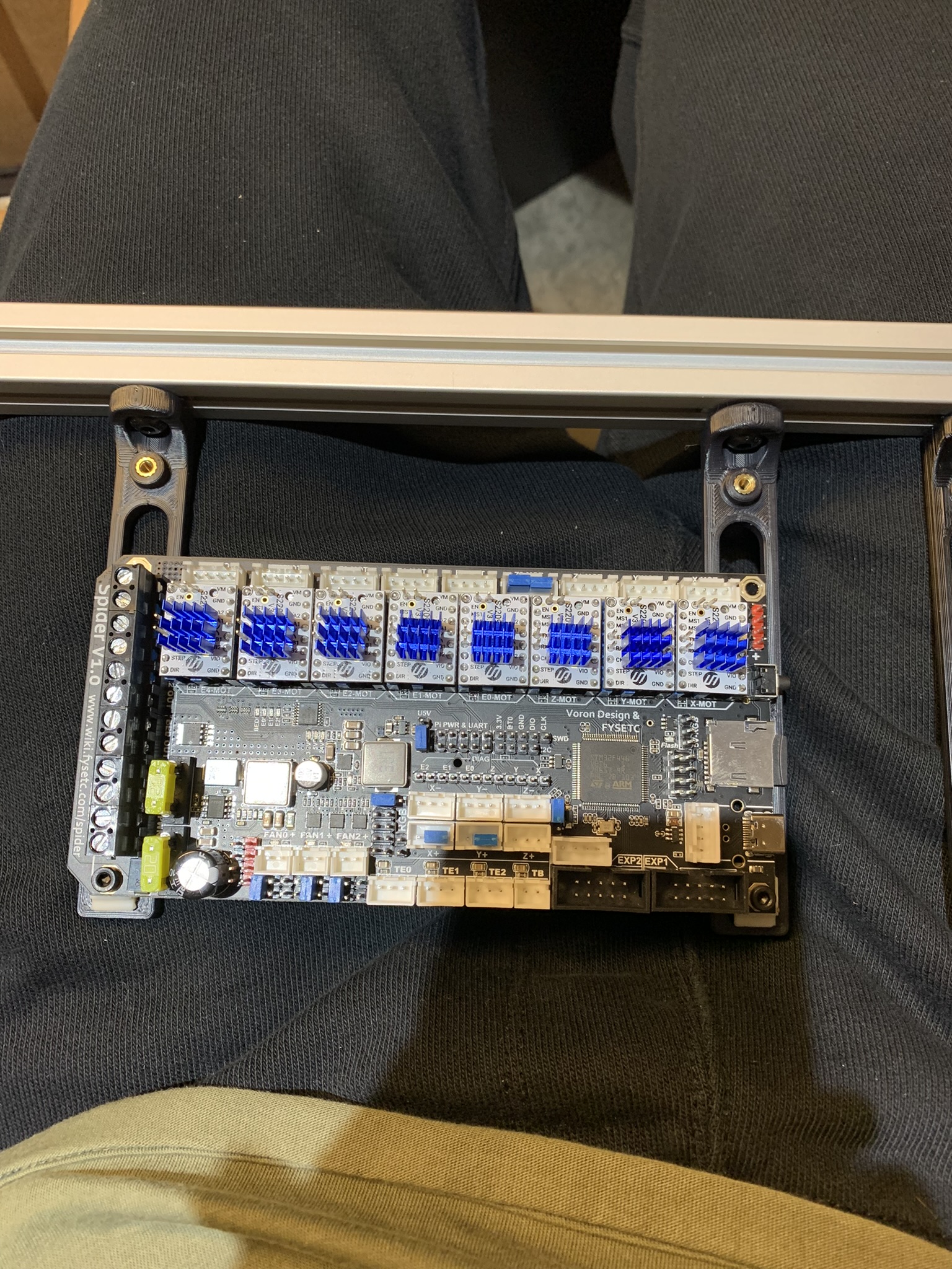
Figure 22: Controller attached to extrusion for alignment
Slide the controller up and into place, and attach it to the main pieces using 2x M3x8 SHCS.
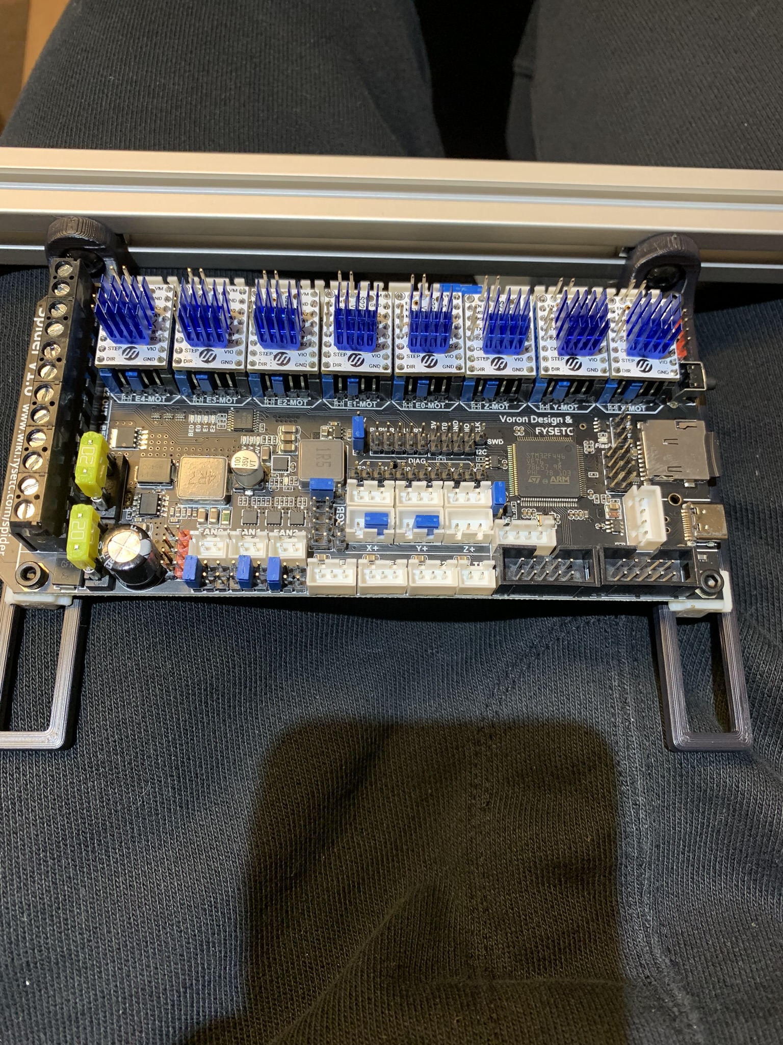
Figure 23: Controller completely attached to the extrusion
Repeat this process for the expander board. Insert your USB cable into the main controller to make sure that you leave enough room between it and the expander board.
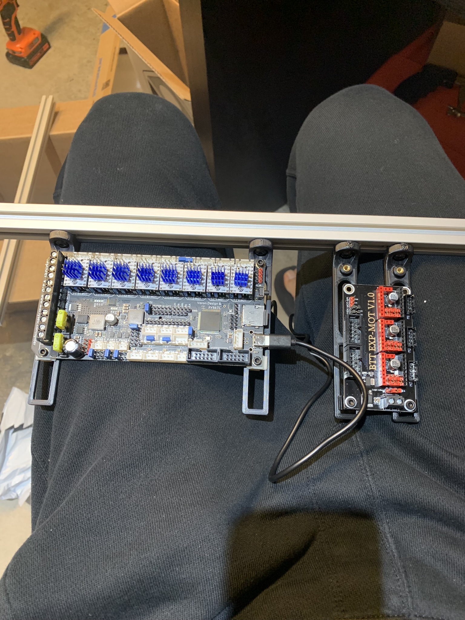
Figure 24: Controller and expander attached to the extrusion with enough space between them
Corners
Insert 6x M5 heatset inserts into these holes:
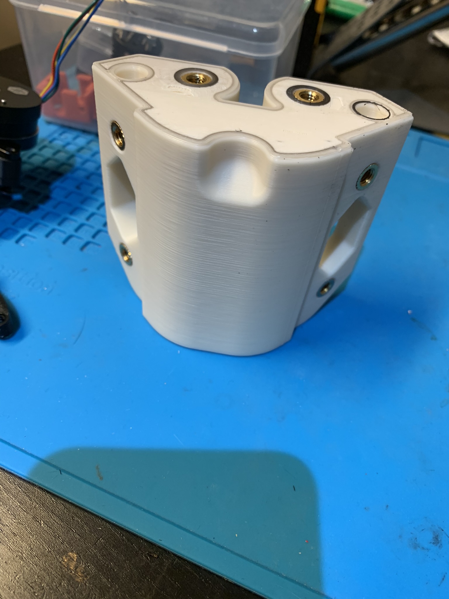
Figure 25: M5 heatset inserts for backpack corners
Insert 1x M3 tall heatset insert into the remaining hole:
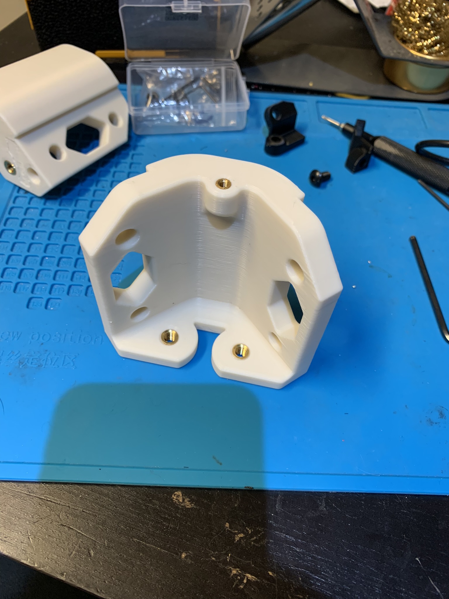
Figure 26: M3 heatset inserts for backpack corners
Attach the corners to the back panel with 2x M5x10 BHCS each.
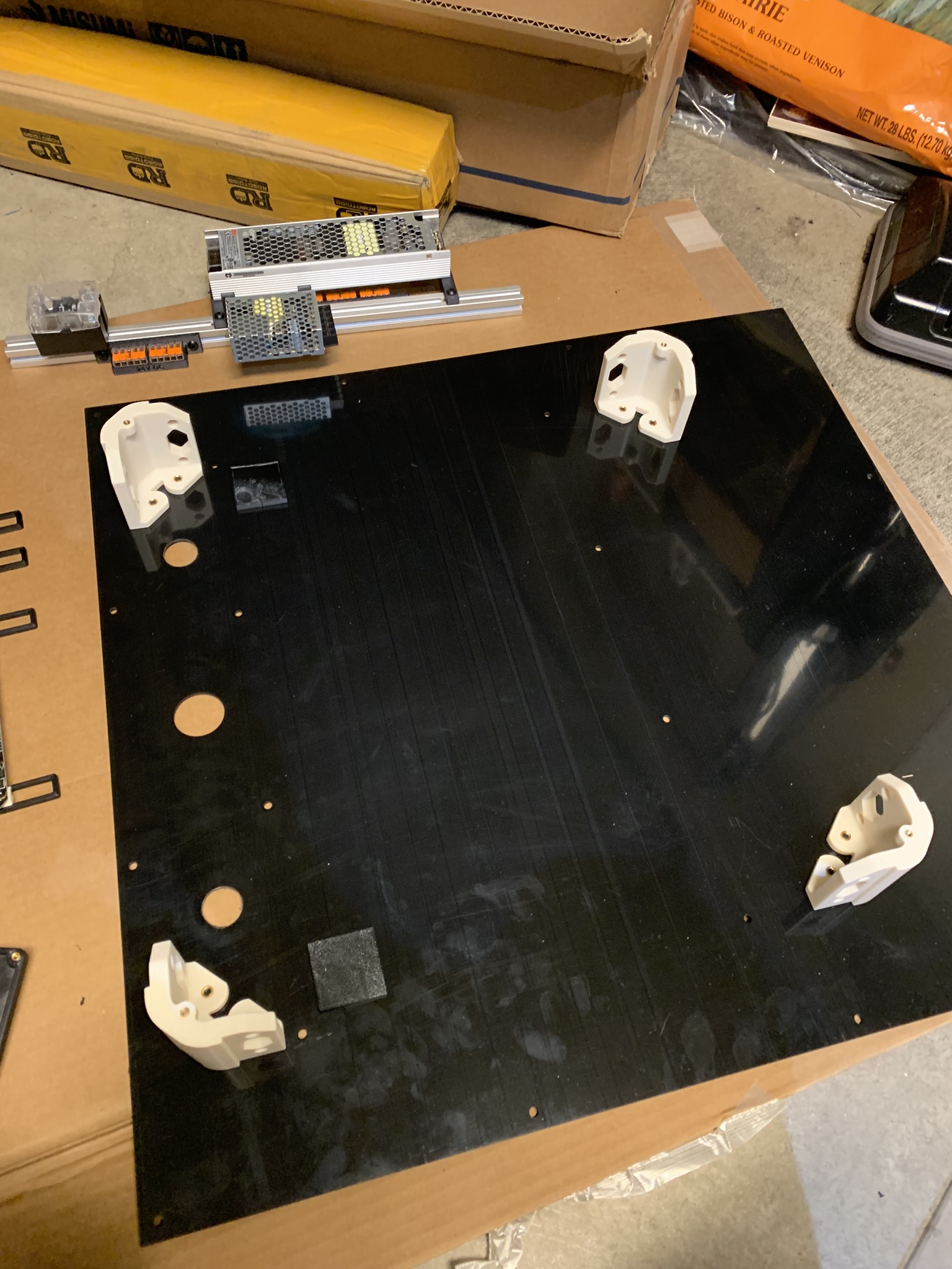
Figure 27: Backpack corners attached to back panel
Installing the back panel
Note I did this backwards during my build and attached the electronics-mounting extrusions to the panel before attaching the panel to the printer, so the following pictures will have the extrusions already installed. Just ignore that part and focus on the panel. I thought about the entire process while I was writing this build log, and I believe that you’ll have an easier time if you install the panel first, so that’s how I’m structuring this post.
I wanted my back panel to be held in using roll-in nuts, but starting off the installation with roll-ins is hard because it’s a heavy panel, and holding it in place with one hand while adjusting roll-ins with the other is cumbersome. I recommend you start with hammer head nuts, and then - if desired - you can switch to roll-ins later, once the panel is partially attached to the frame.
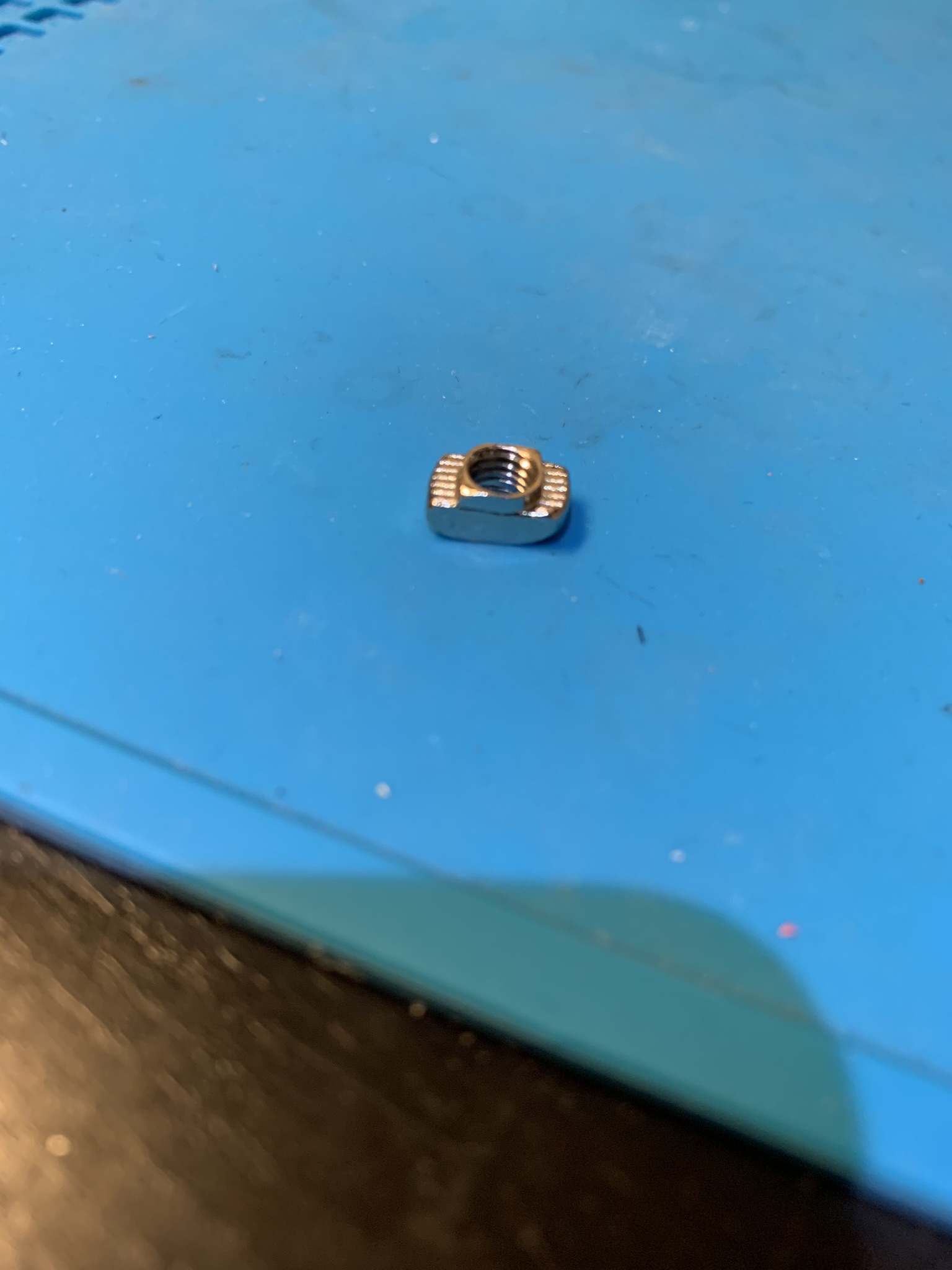
Figure 28: Close up of a hammer head nut
Place spacers along the top and bottom sides and insert 4x M5x10 BHCS bolts through the panel and spacers into hammer head nuts. If you plan to use hammer heads long term for the back panel (as opposed to switching them out with roll-ins) then put the side spacers as well as all required bolts at this stage.
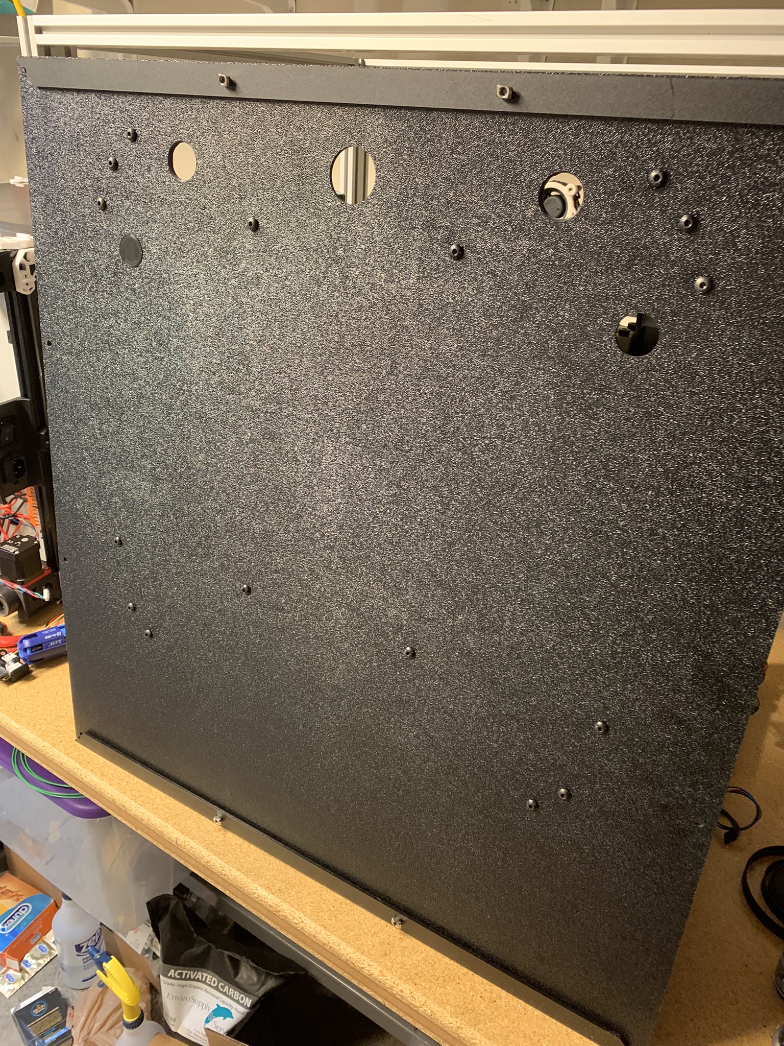
Figure 29: Back panel with top and bottom spacers held together with hammer head nuts and M5 bolts
Insert the nut side of the panel into the back face of your printer, secure the top and bottom sides by tightening the bolts. Start inserting roll-in nuts into the left and right vertical extrusions and position them by gently flexing the back panel. You won’t be able to roll them past the through holes made into the extrusions at gantry height, so the lower ones will have to be inserted at the bottom of the printer.
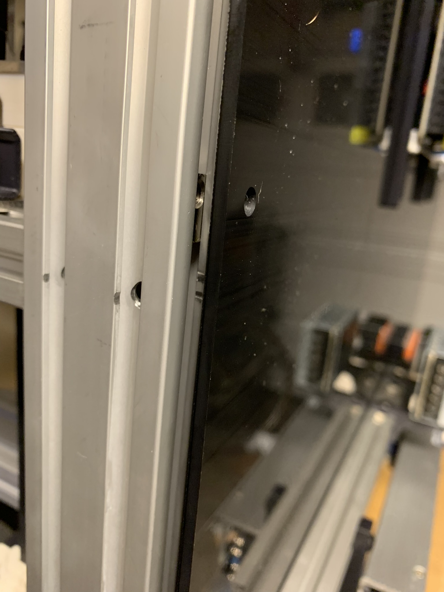
Figure 30: Positioning roll-in nuts for side extrusions by flexing the back panel
Insert the spacers and use M5x10 BHCS to secure the sides, and then you can remove the top and bottom bolts and nuts, place roll-ins in and replace the bolts. Positioning the roll-ins is similar to the previous step, you’ll have to gently flex the panel.
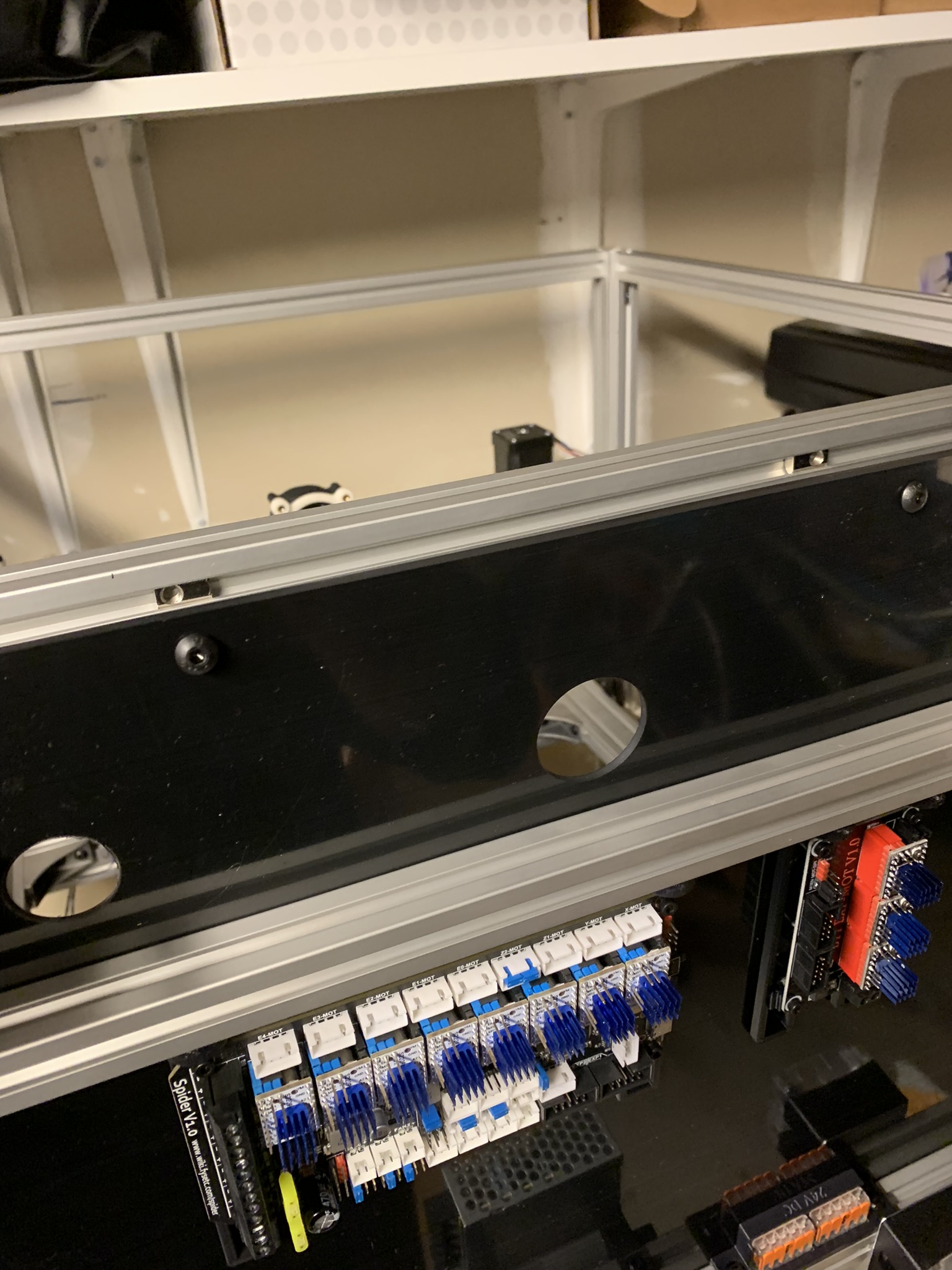
Figure 31: Positioning roll-in nuts for top and bottom extrusions by flexing the back panel
Installing the extrusions
Note - Ignore the square black printed pieces you see on my panels in the following pictures. The backpanel DXF changed after I’d placed an order for my panels, so mine came with holes that overlap with motor locations. I drilled holes at the right locations, and printed pieces to plug the faulty holes, those printed pieces are what you’ll see in my pictures.
I recommend using hammer head nuts instead of roll-ins for this. You’ll have a really hard time positioning roll-ins correctly. Insert 4x M5x8 BHCS (eDrawing says M5x10 while I’m writing this, and it’s incorrect) through the back panel and lightly screw hammer head nuts onto them.
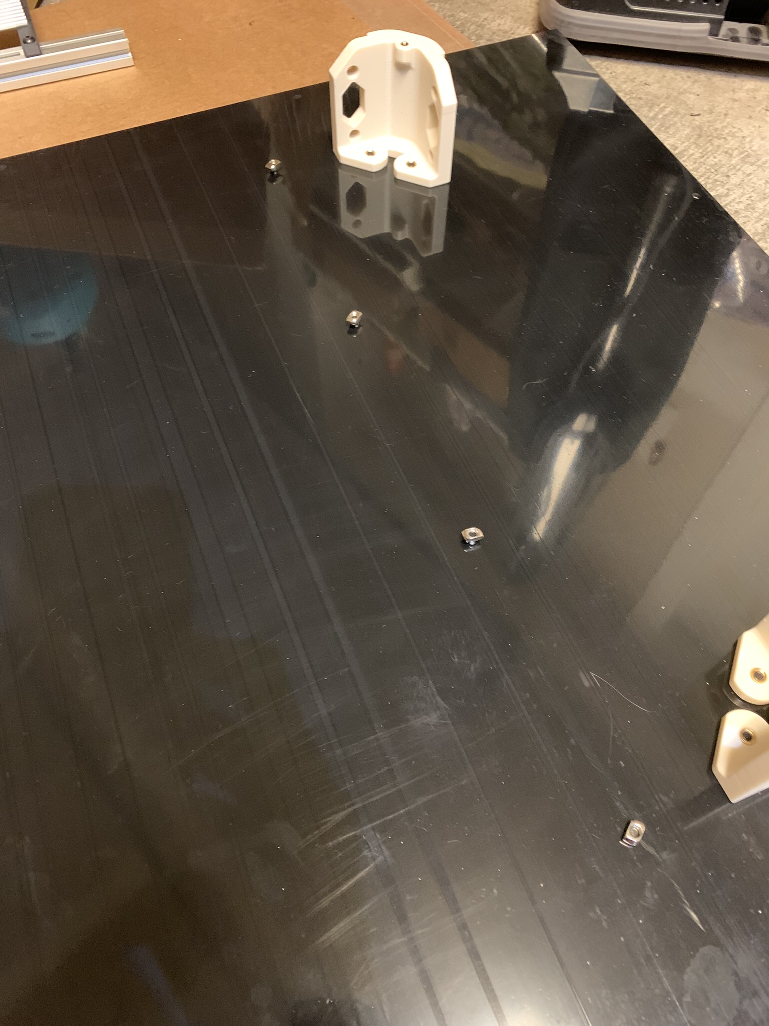
Figure 32: Bolts and hammer head nuts through back panel
Slide one of the electronics-mounting extrusions onto the nuts.
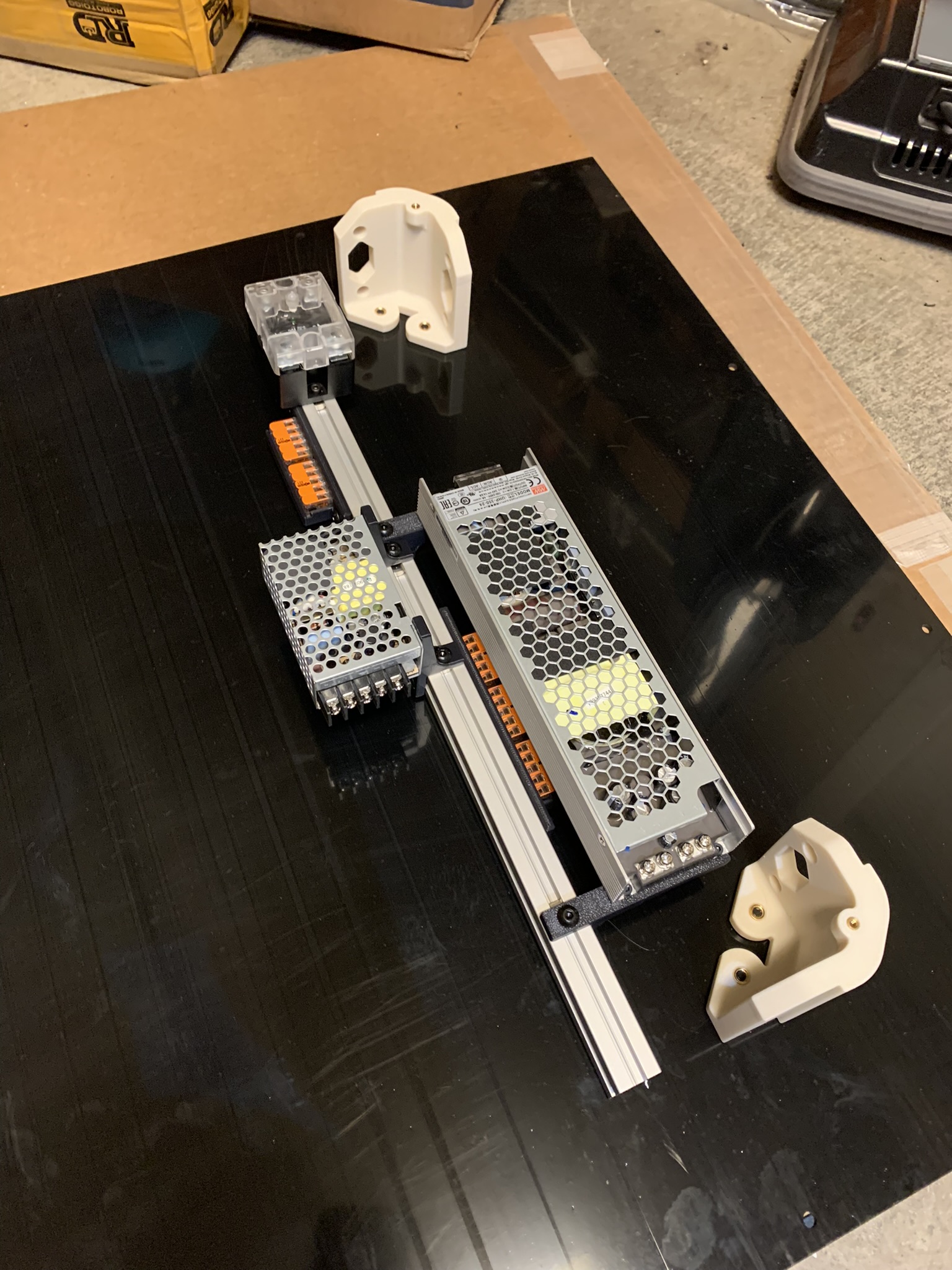
Figure 33: First electronics extrusion attached to back panel
Position it so that the ends don’t stick past the corners. Tighten the bolts.
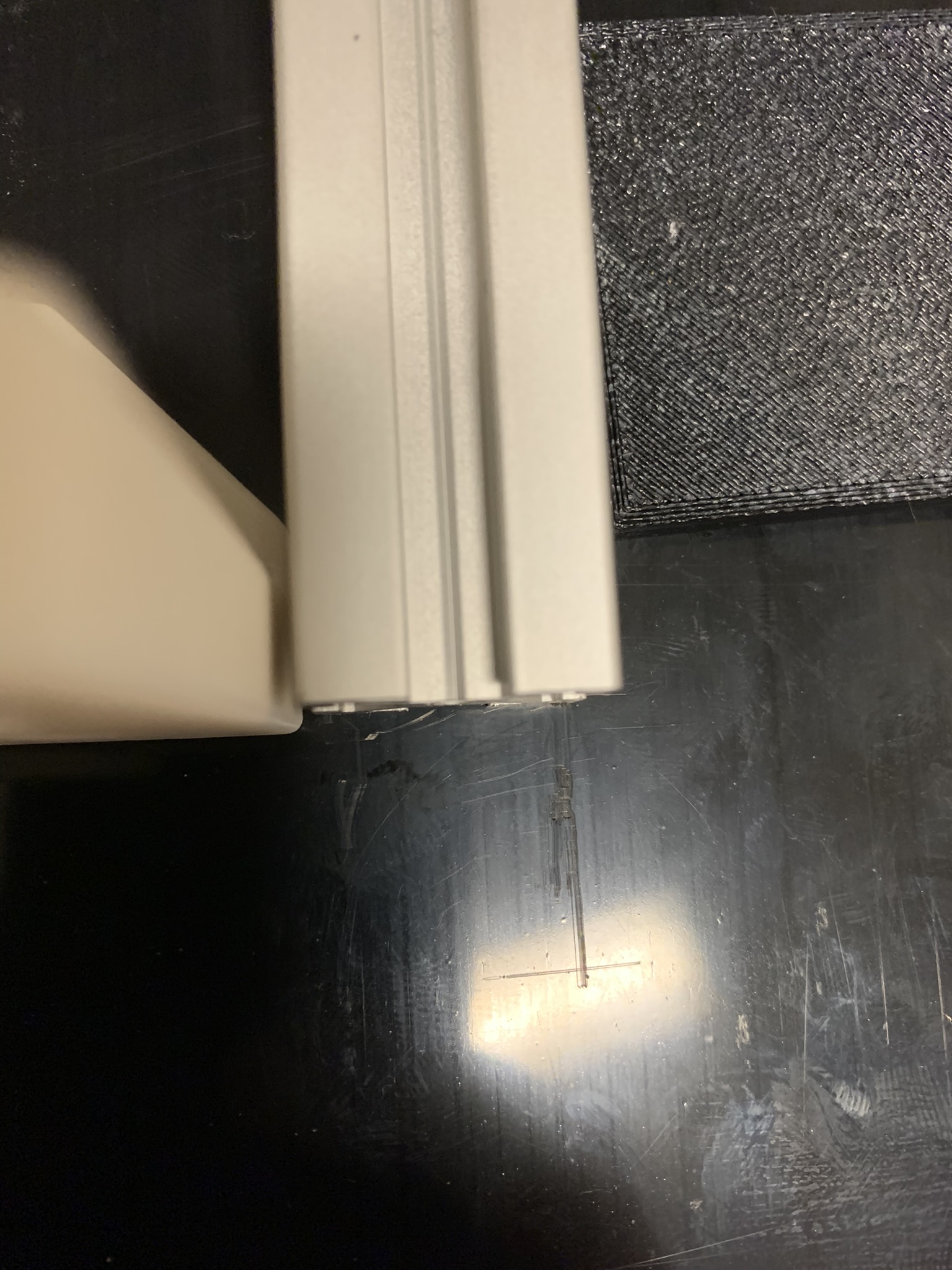
Figure 34: Close up of one end of the just-installed extrusion
Install the second one in an identical fashion.
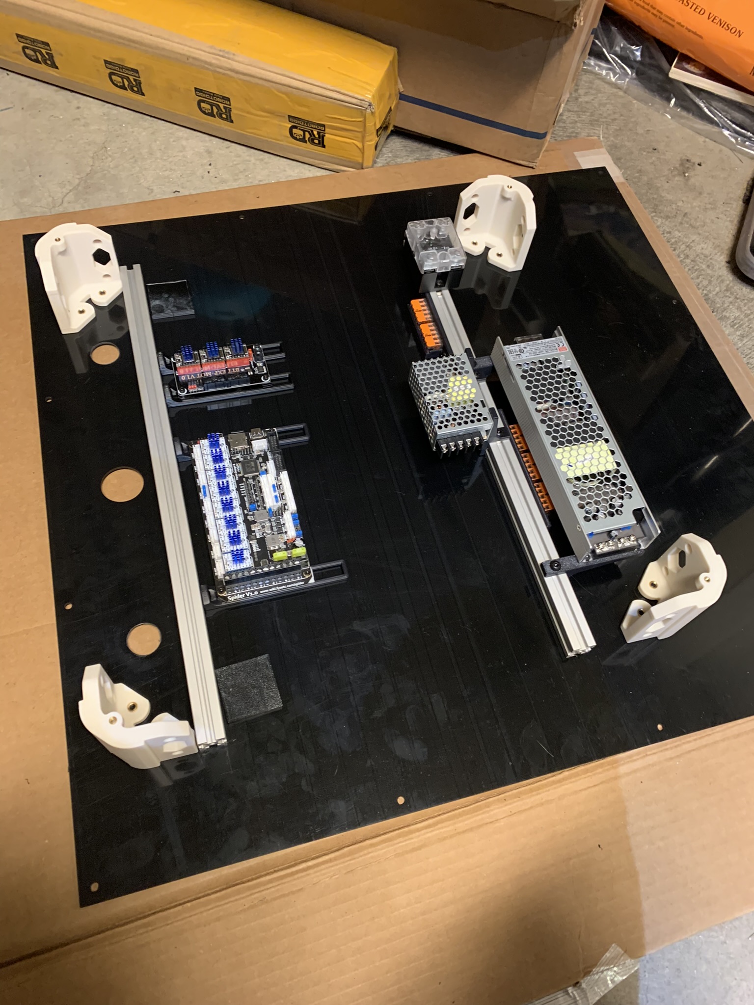
Figure 35: Second electronics extrusion attached to back panel
Your panel should already be on the frame if you followed my advice and did that first. If you didn’t, go follow the advice in the last section to install your panel.
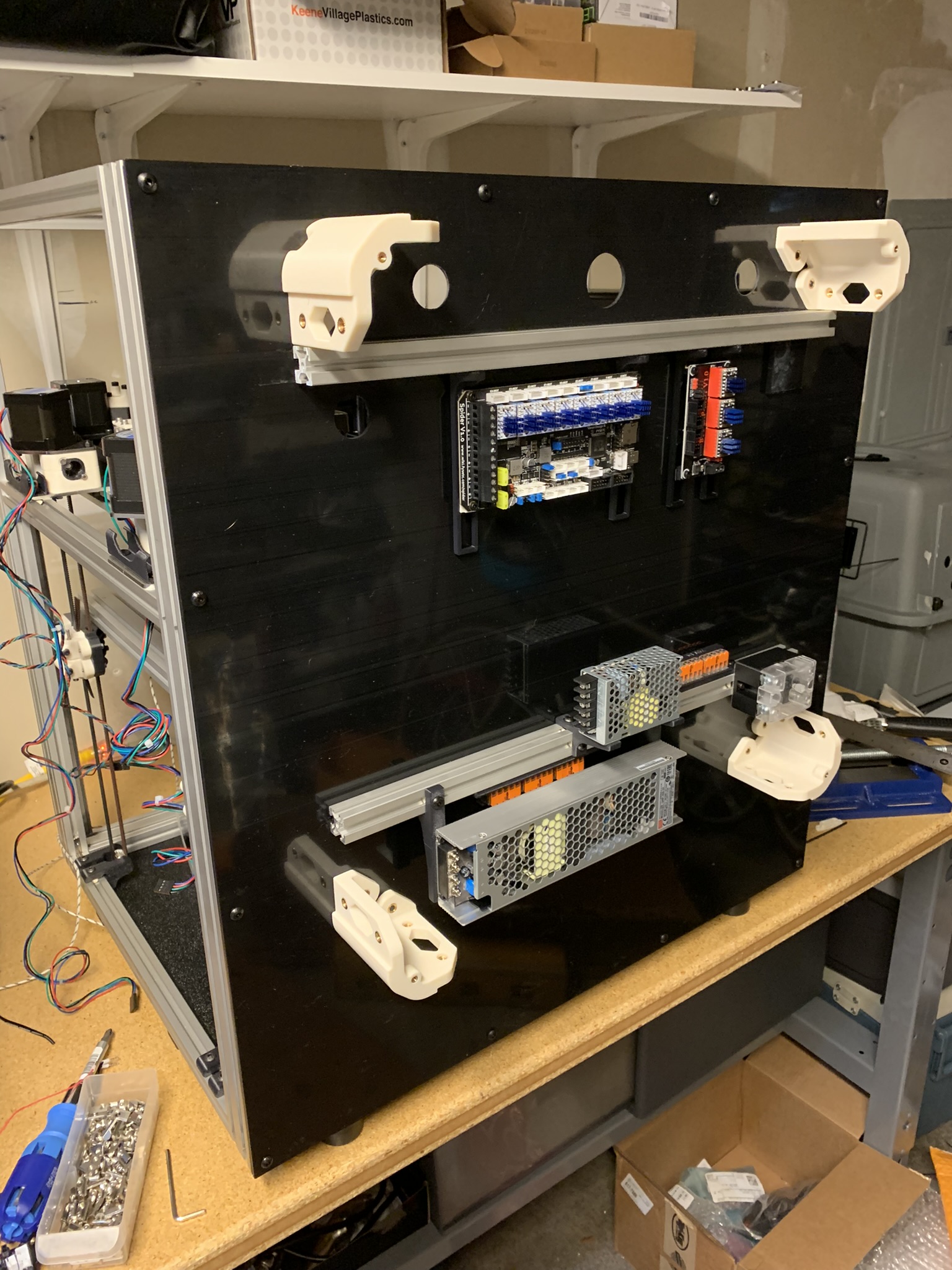
Figure 36: Backpack attached to back panel
Grommets
Insert the grommets into the back panel. The hex side should be inside the backpack
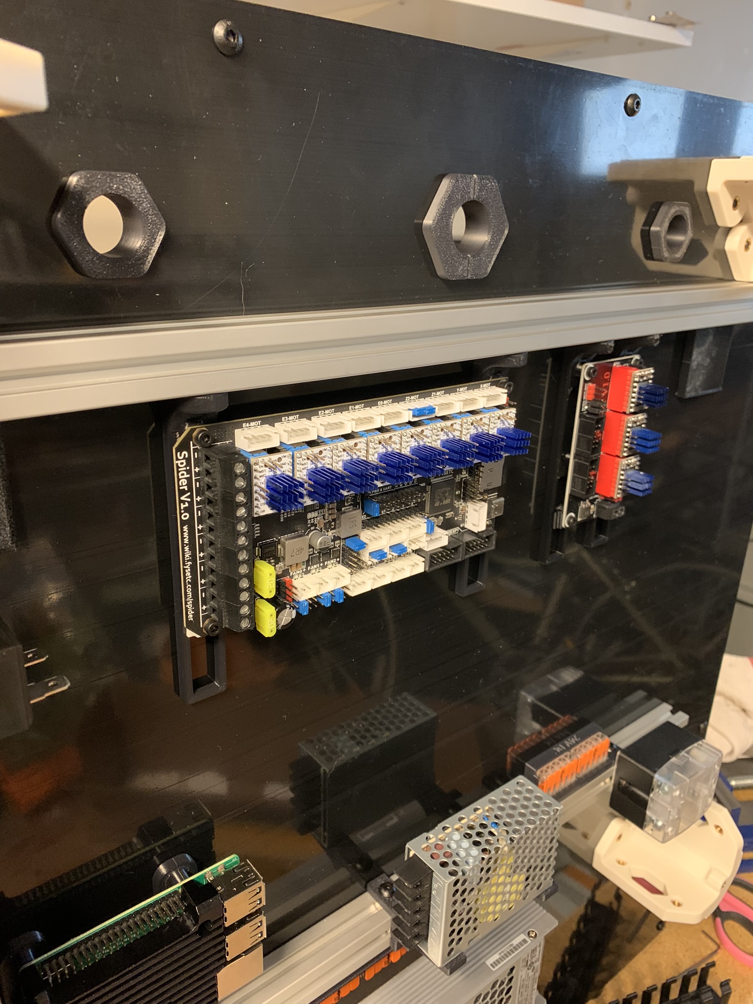
Figure 37: Grommets inserted into the back panel
Screw in the other halves of the grommets
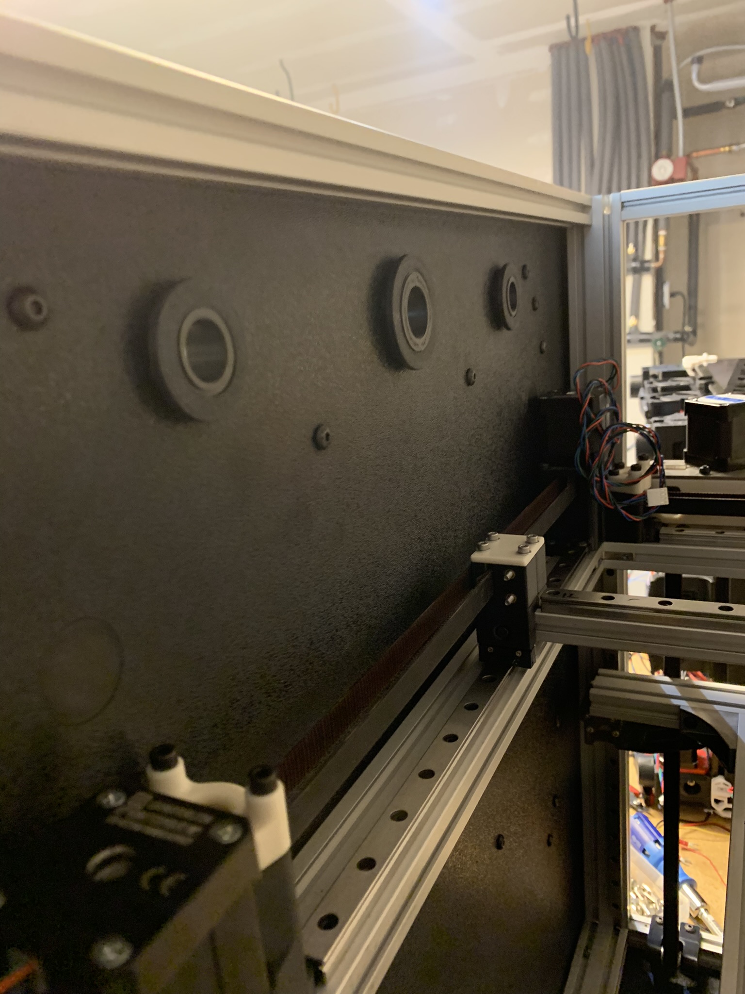
Figure 38: Other halves screwed onto grommets
Power inlet
Insert 2x M3 tall heatset inserts into the printed part.
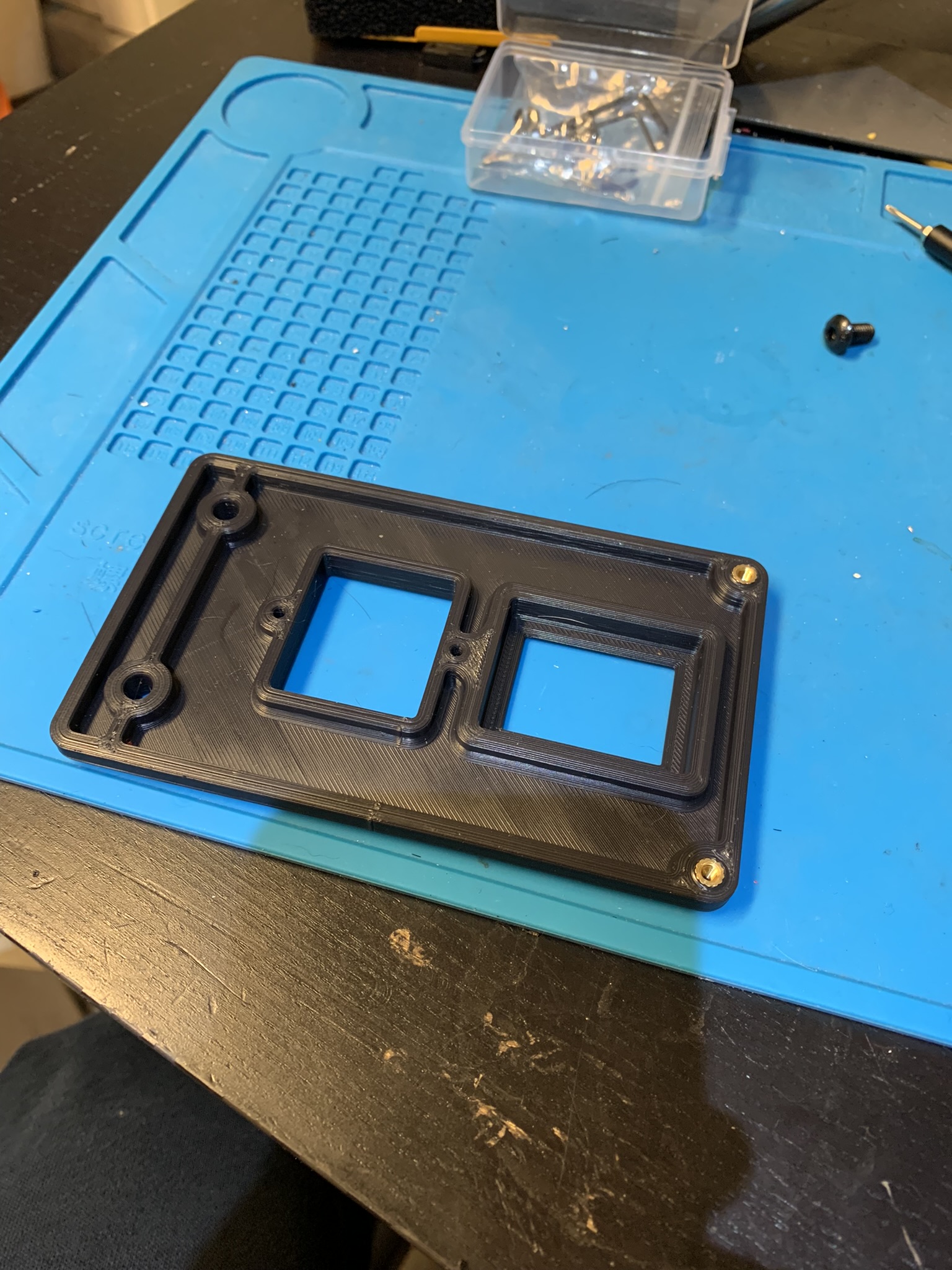
Figure 39: Heatset inserts installed into power panel
Insert the power inlet and rocker switch into the panel.
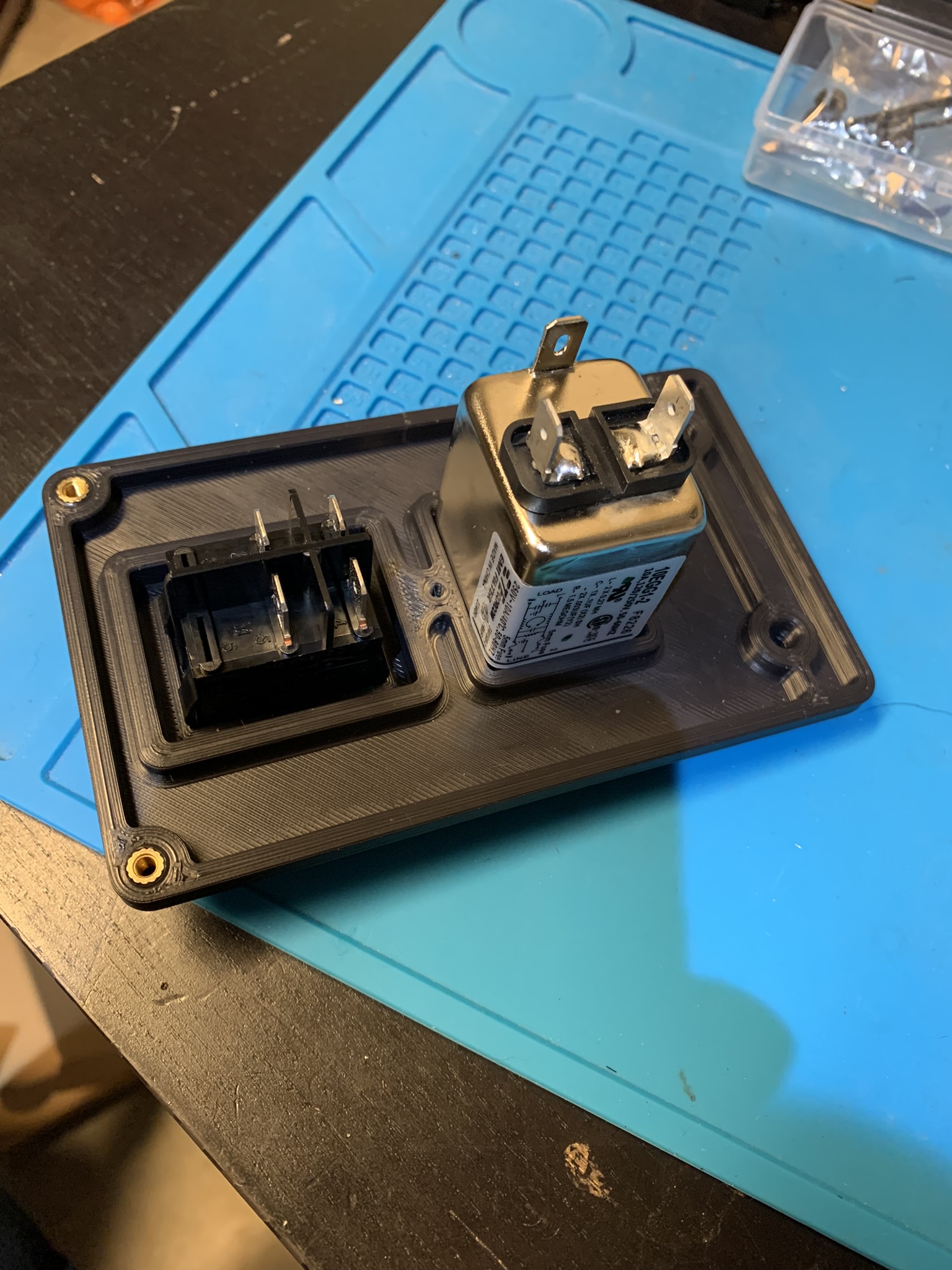
Figure 40: Power inlet and rocker switch inserted into the panel, rear view
Use 2x M3 tapping screws to attach the plug to the panel. Pop the fuse holder out, I used a flat head screw driver to lever it out.
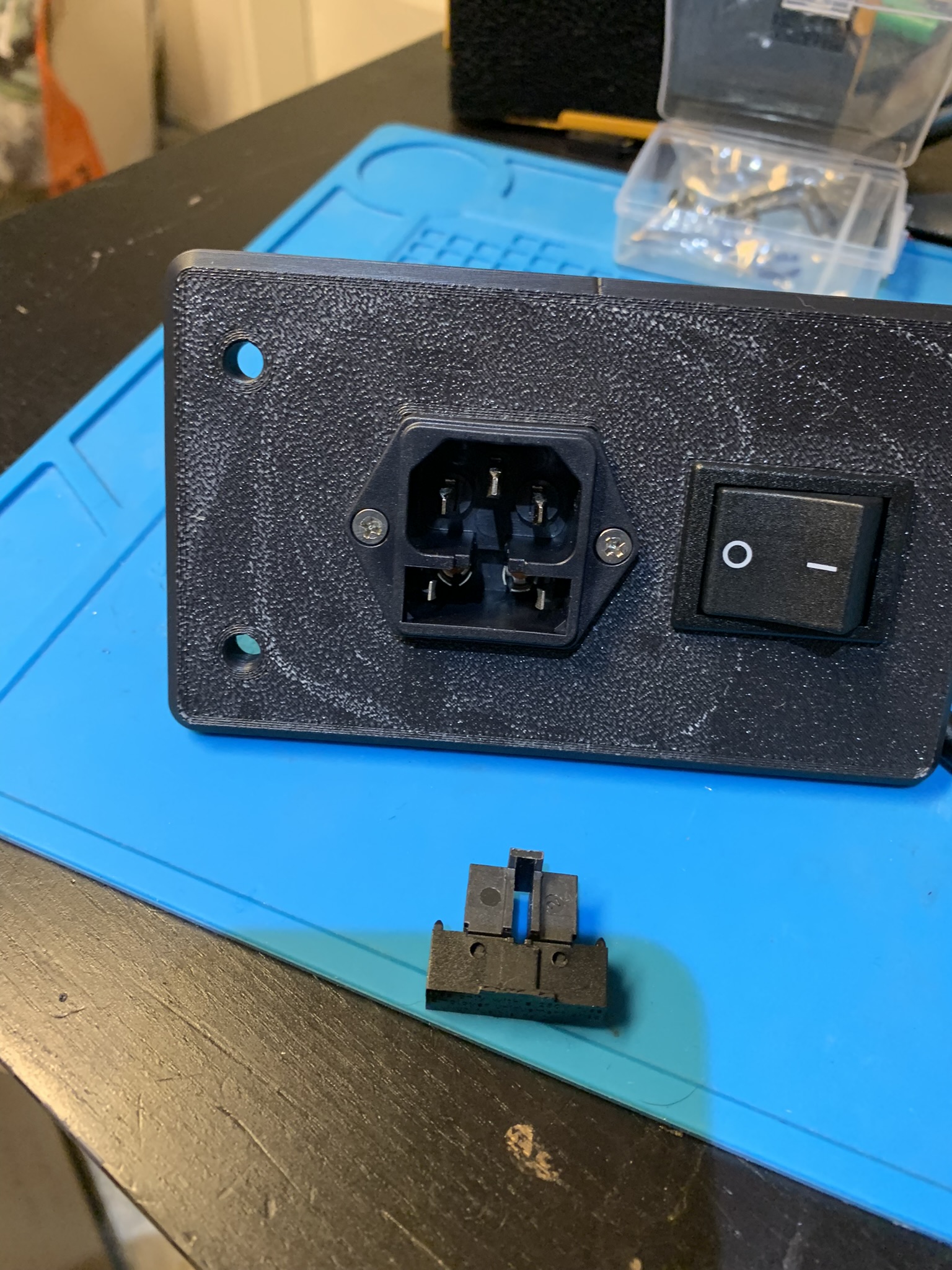
Figure 41: Fuse holder removed from the power inlet
Put two fuses into the fuse holder and pop it back into the power inlet.
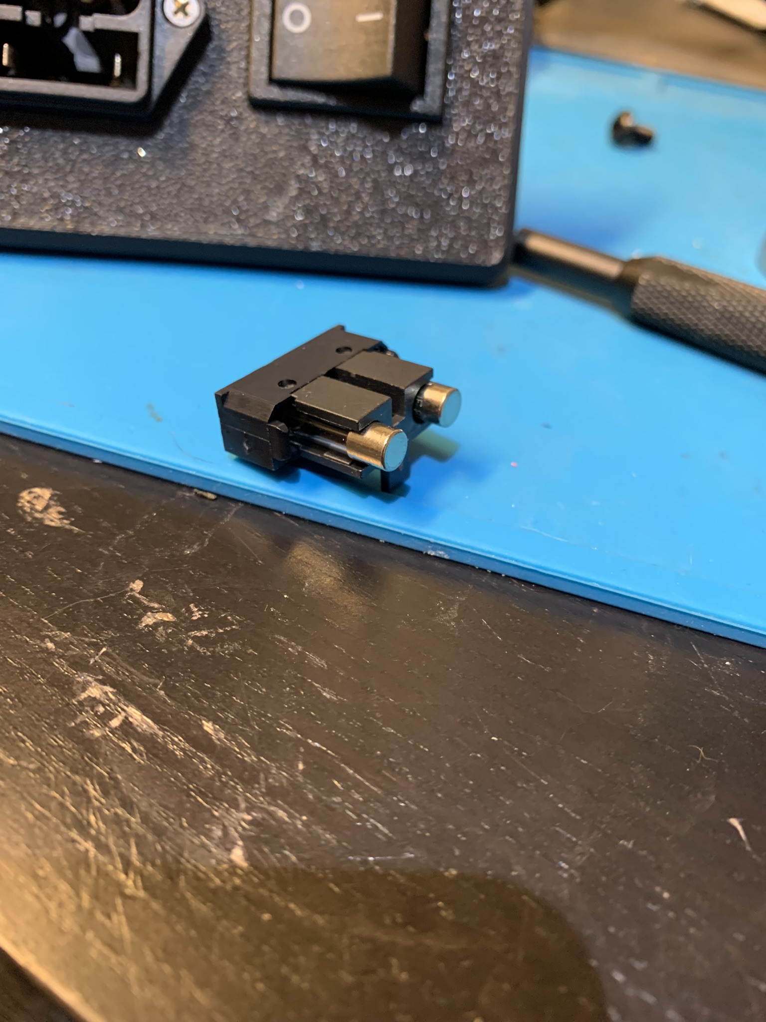
Figure 42: Fuse holder with fuses inserted
Blanking plates
By default, the side panel with the power inlet has two blanking plates. You can substitute either with a plate of your choice. I substituted one with a plate that has space for an hour counter, a keystone jack and a bowden inlet. It’s this mod with some added holes so that I can screw the hour counter in. Insert 4x M3 Tall heatset inserts into each plate
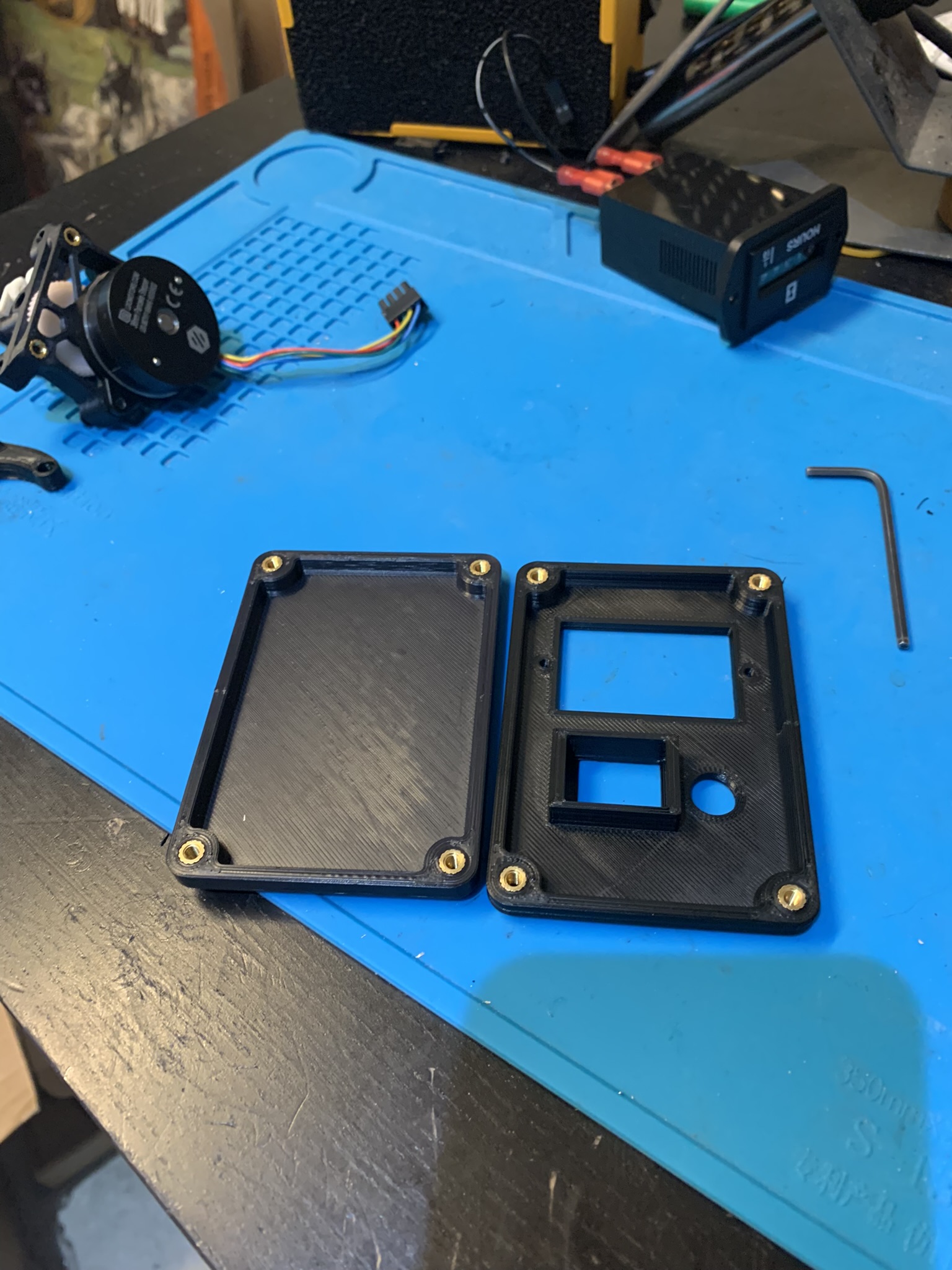
Figure 43: Heatset inserts installed into electronics blanking plates
Populate the plate(s) if applicable
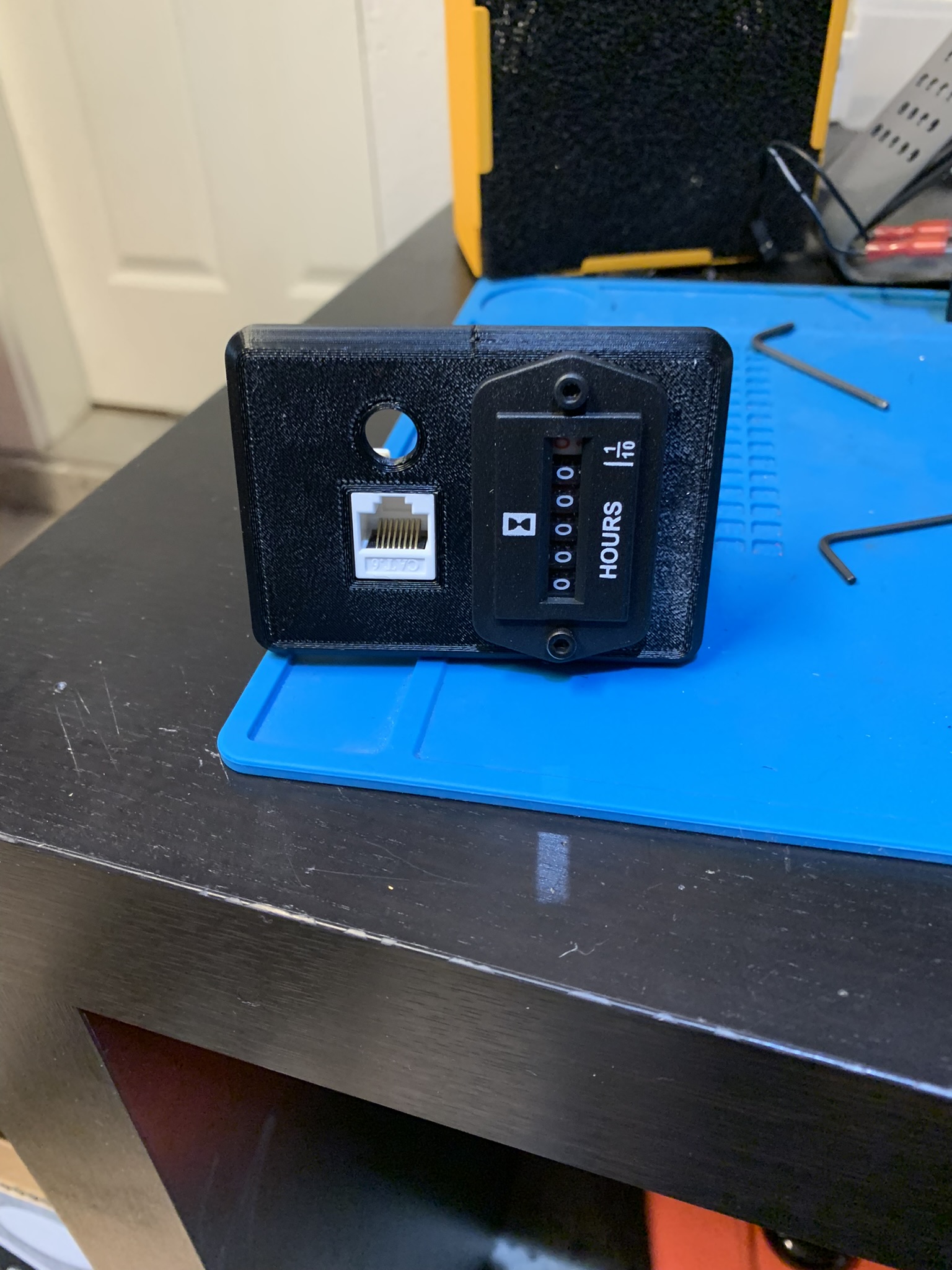
Figure 44: Hour counter and keystone jack inserted into blanking plate
Installing the side panels
Attach the power inlet plate and blanking plates to the laser cut side panel piece using 4x M3x10 SHCS each on the inside, then attach the panel to the corners using 4x M5x10 BHCS.
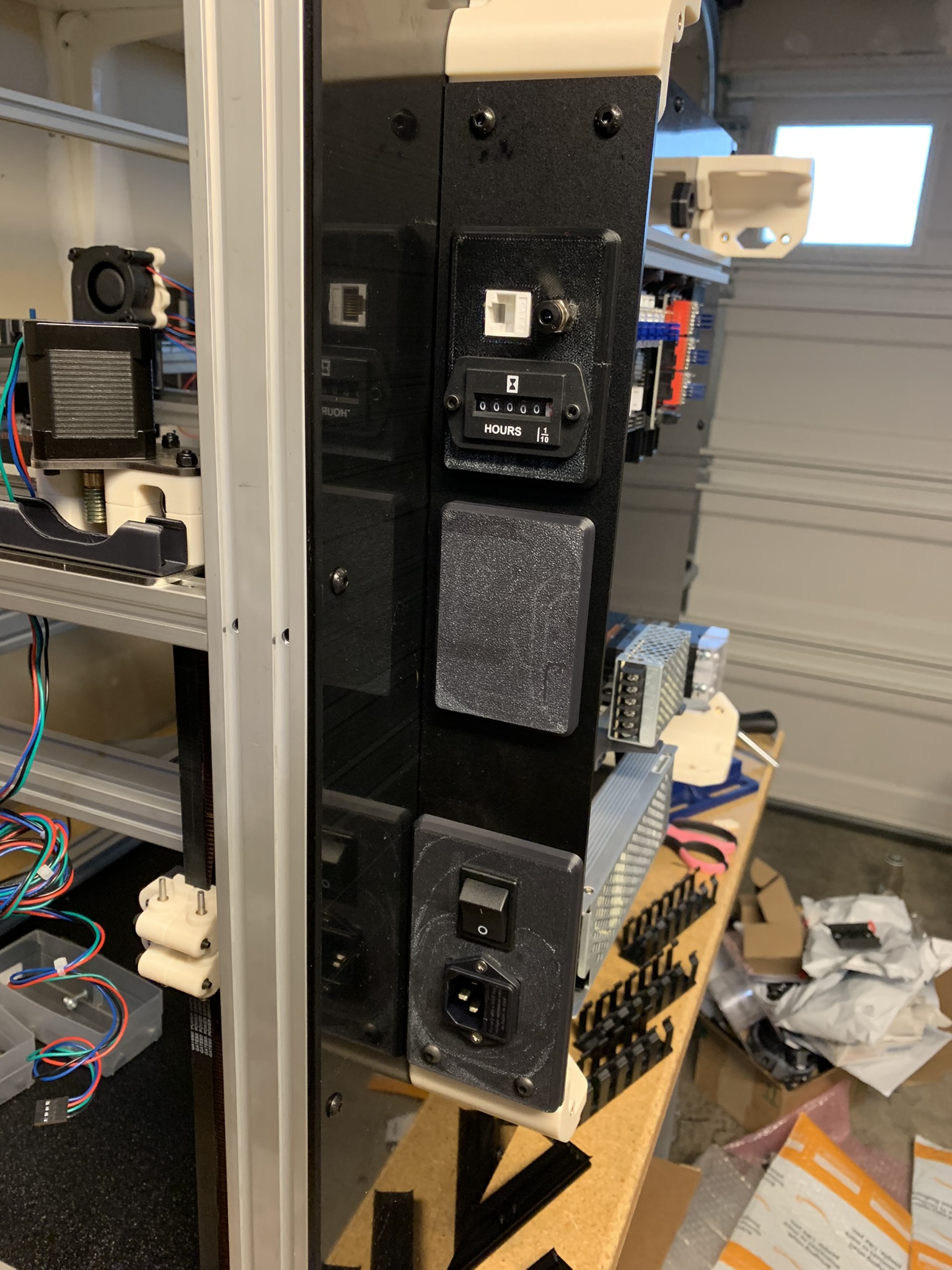
Figure 45: Side panel with power inlet installed on backpack
Should you choose to, you can also install the other three side panels at this time. However, I recommend doing that after you’re done with wiring. I broke a chunk out of one of my side panels by accidentally smacking it with wire strippers.
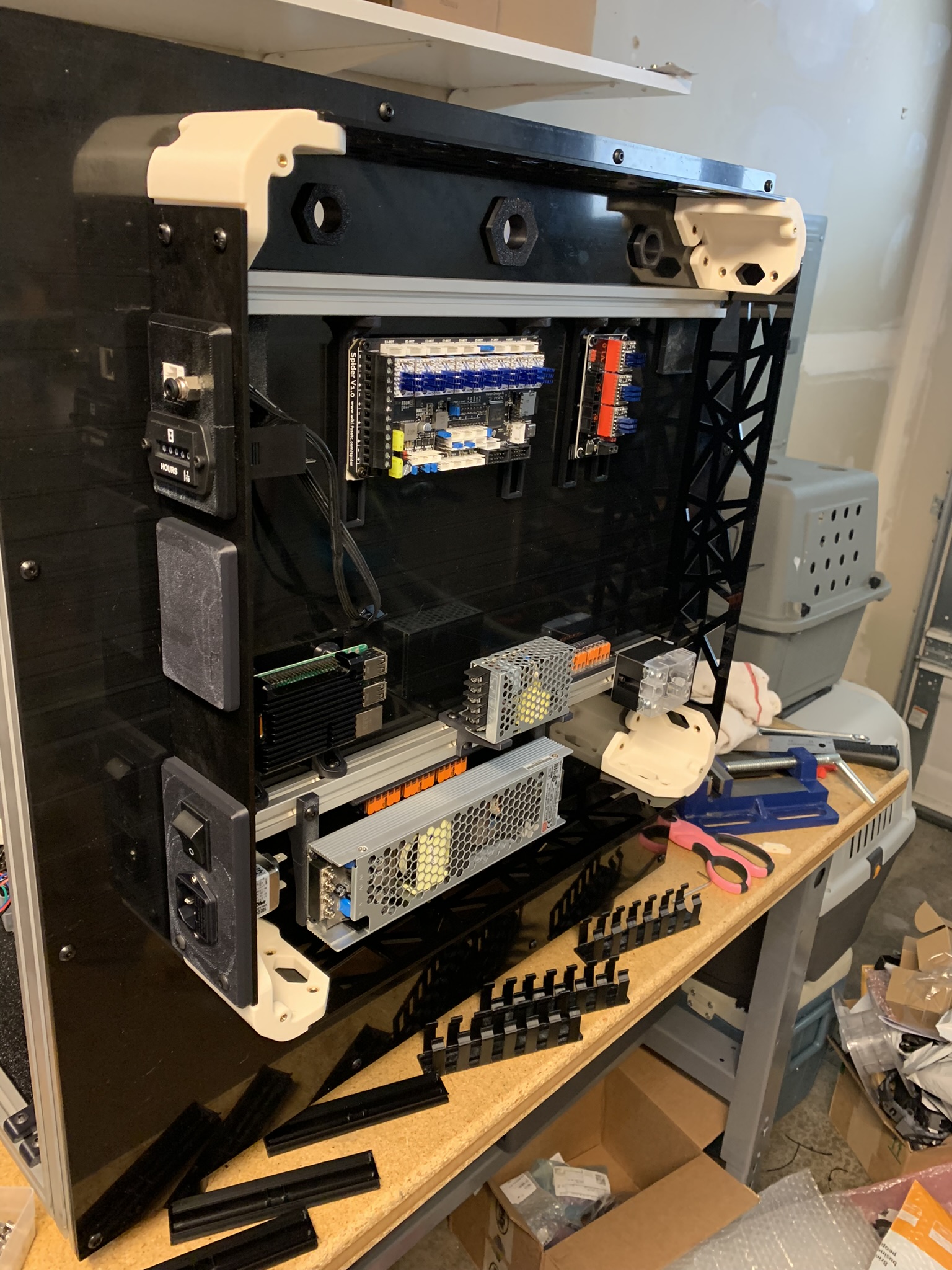
Figure 46: Other side panels installed on back