K2 Build Log Part Three: Z Drives
Mar 4, 2022BOM
For each Z drive, you will need:
- Printed parts
- Laser-cut stainless steel parts, bottom and top
- Motor
- 4x M4x45 SHCS
- 2x M3x45 SHCS (the eDrawing said M3x40 when I built mine, but those were too short)
- 2x M3x8 SHCS
- 2x M3x8 Flat-head or Pan-head tapping screws
- 1x Worm gear
- 1x Spur
- 1x Thrust bearing
- 1x 5mm x 60mm steel shaft
- 3x 625-2RS bearings
- 1x 9mm toothed pulley
- 2-3x M5 x 3mm spacers
- 1-4x M5 x 1mm shims/washers
The variable number of spacers at the end is because we might need to make adjustments based on your worm gear and spur.
Before you start
There are two potential issues you might run into if you ordered parts from Aliexpress instead of Misumi, or if you’re using OMC stepper motors instead of LDO ones.
Spur hub length
Check the length of the hub of your spurs. Ones sourced from Misumi are 6mm long. Those sourced from Aliexpress might vary, mine were 7mm.
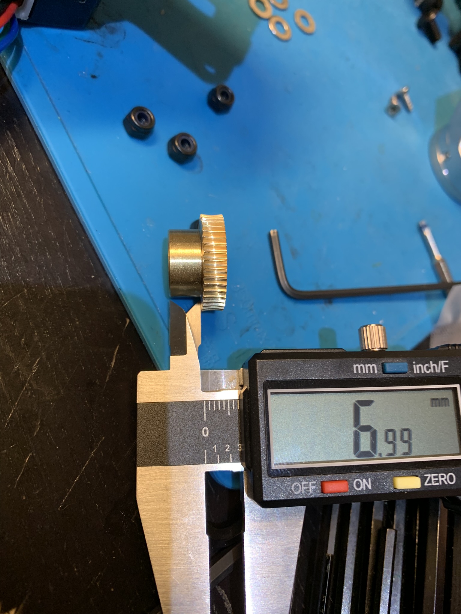
Figure 1: K2 spur hub length
- If yours are 6mm long, you’ll use three 3mm spacers and one 1mm spacer in the shaft assembly
- If yours are 7mm long, you’ll use two 3mm spacers and four 1mm spacers in the shaft assembly
- If yours are a different length, you’ll have to figure out your own spacer combination to center the spur teeth on the worm gear’s teeth. I’ll cover this in a bit more detail later
Worm hub length
Put the thrust bearing onto your motor’s shaft. Put the worm gear on top, aligned such that the hub is towards the motor. Remove the set screw from the worm and rotate the worm until the flat on the motor shaft is under the set screw hole. Take a look inside and check whether the flat is fully under the hole, or if it looks something like this:
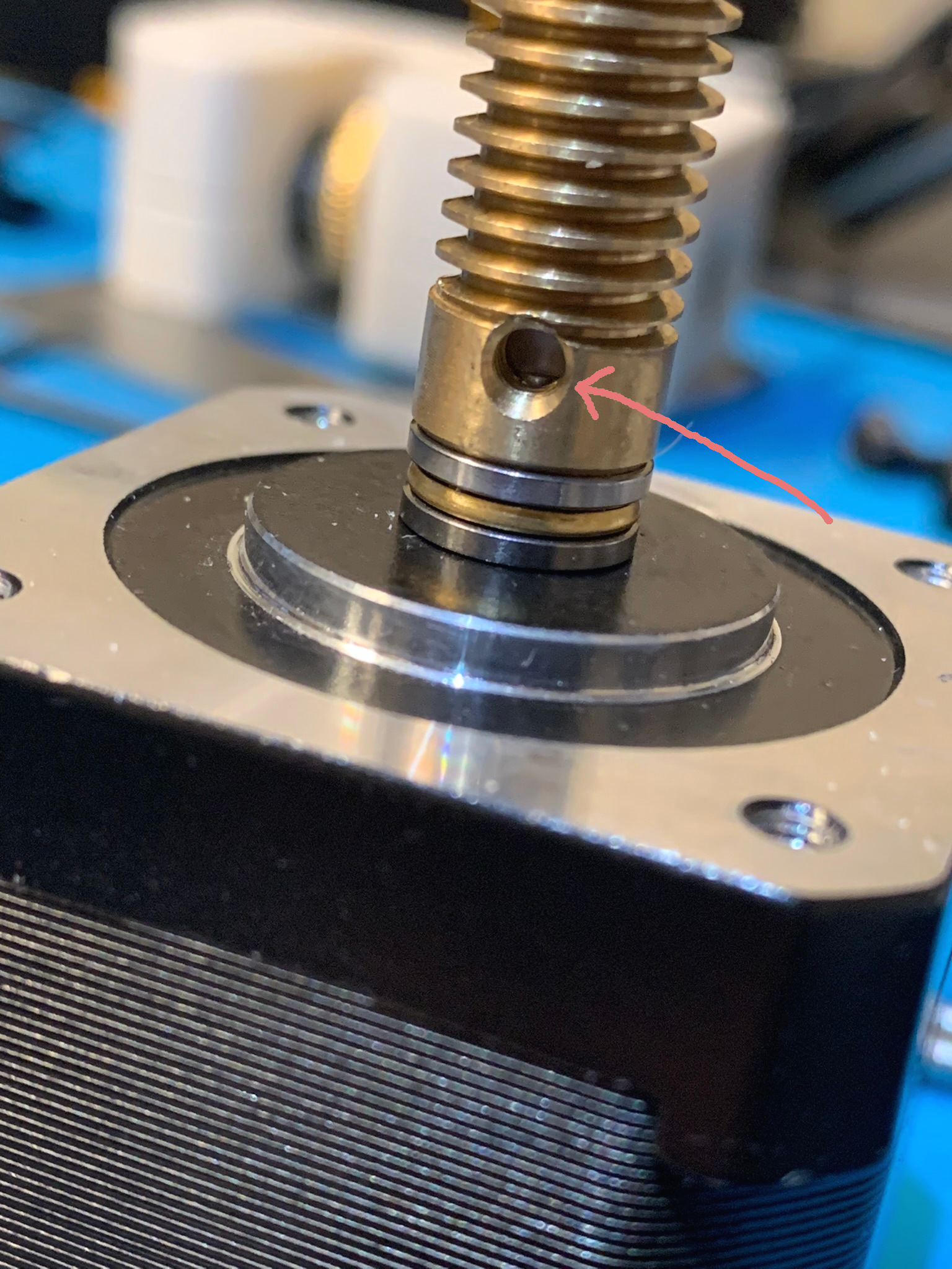
Figure 2: K2 Worm gear with short hub
In the above picture, the hub of the worm is short enough that the flat isn’t fully under the set screw hole. If yours looks like this, you’ll have to add a 1 mm washer on top of the thrust bearing during assembly. This will raise the worm gear enough that the set screw will fully screw into the flat on the motor shaft.
Motor assembly
Prep
Add some loctite to the threaded portion of 2x M3x45 SHCS and 2x M3x8 SHCS and set them aside to dry.
Thrust bearing
Grease the thrust bearing. I used a syringe with a blunt tip needle to inject Mobil EP2 grease between each bearing. Once you’re done, install it on the motor as follows:
Put the first part on with the groove up and the flat side towards the motor:
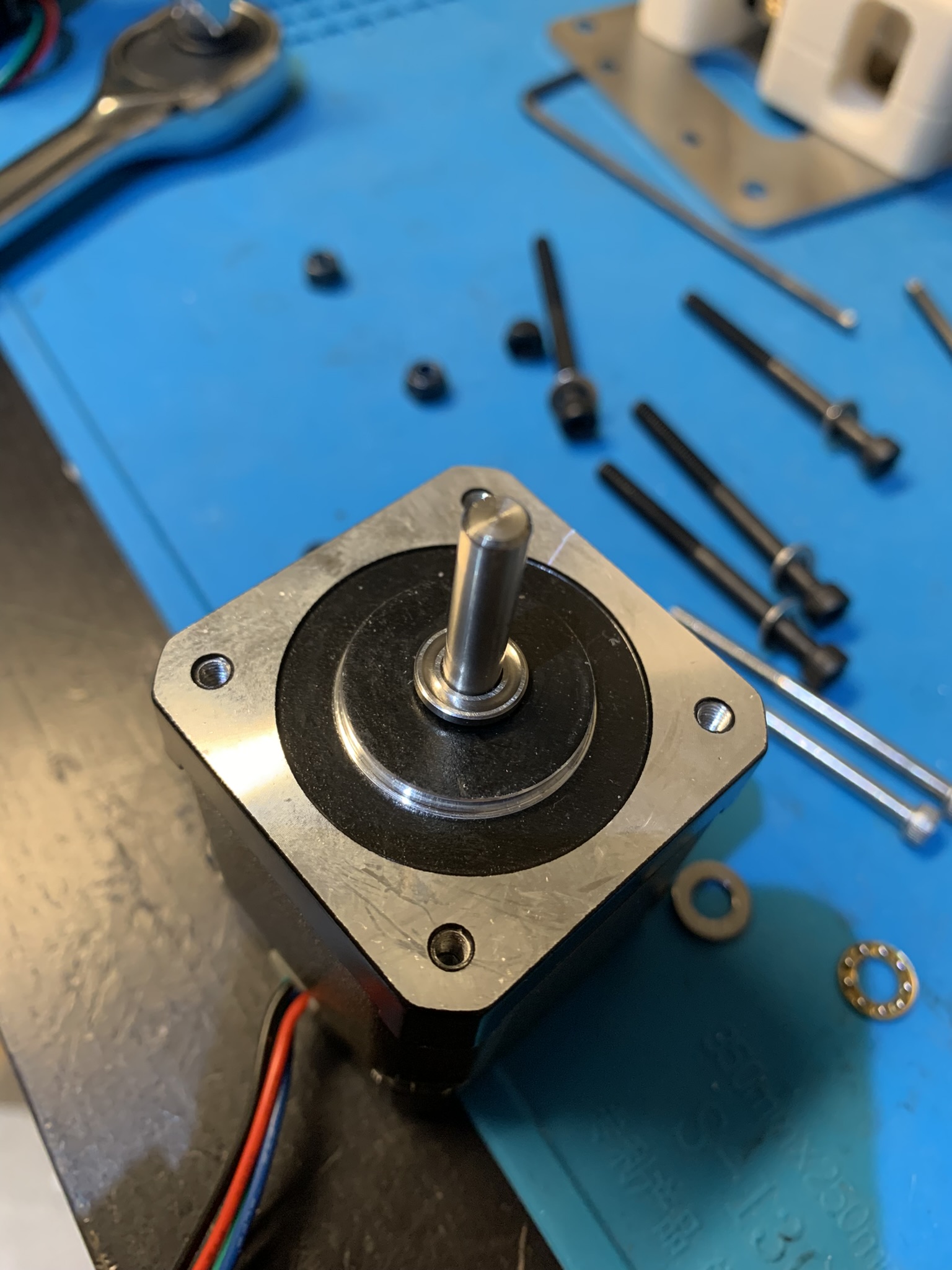
Figure 3: Thrust bearing installation part one
Put the actual bearing part on. I don’t know if the orientation matters, I installed mine with the balls facing away from the motor:
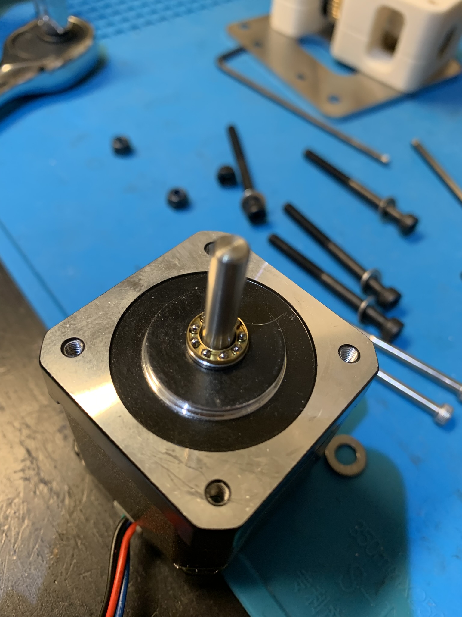
Figure 4: Thrust bearing installation part two
Put the last part on with the groove down and the flat side away from the motor:
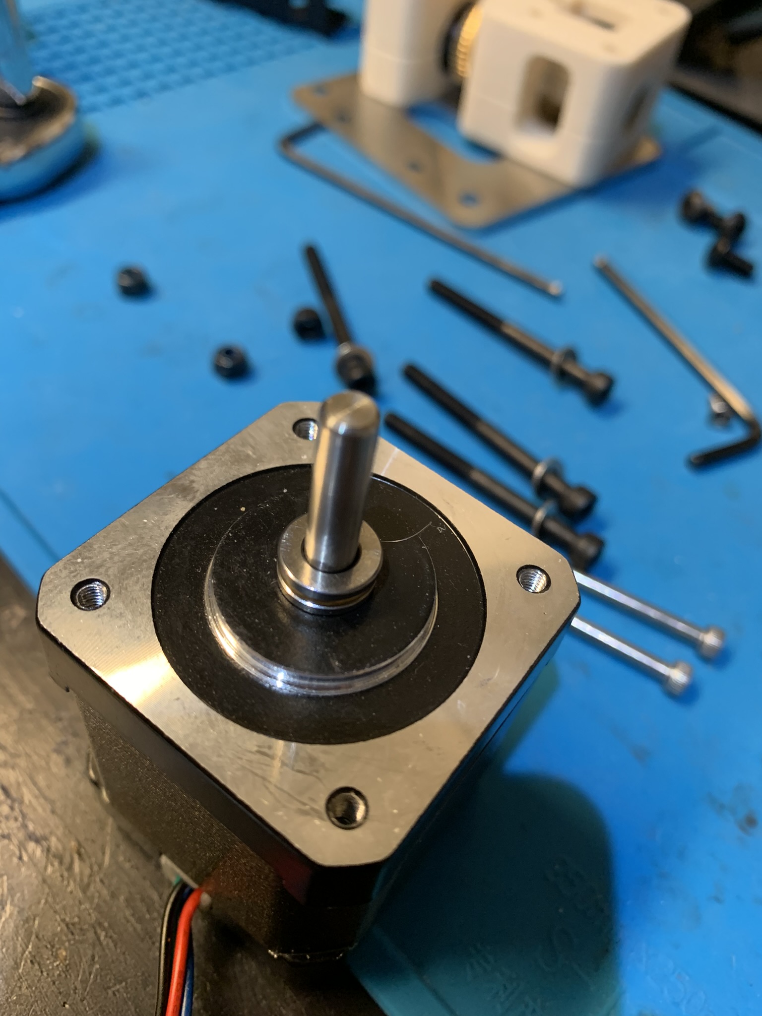
Figure 5: Thrust bearing installation part three
At this point, add a 1 mm washer on top if your hub length is problematic as described above. Otherwise, it’s time to prepare the worm gear for installation.
Worm gear
The worm gear receives rotational as well as axial forces during operation. The set screw mostly stops the worm from rotating independent of the shaft, but nothing constrains it from moving axially away from the motor. In order to prevent this, we need to use some shaft retaining compound. I used Vibra-tite green.
NOTE - Shaft retaining compounds can be really hard - verging on impossible without a blowtorch - to remove, so be prepared to replace the motor, bearing and worm if you need to replace any one of those three in the future.
Take the set screw out of the worm and squeeze some shaft retaining compound into the inside of the hub side of the worm. Wipe away any excess from the bottom of the worm. For example, in the picture below I had some compound on the bottom (which I wiped away after taking the picture)
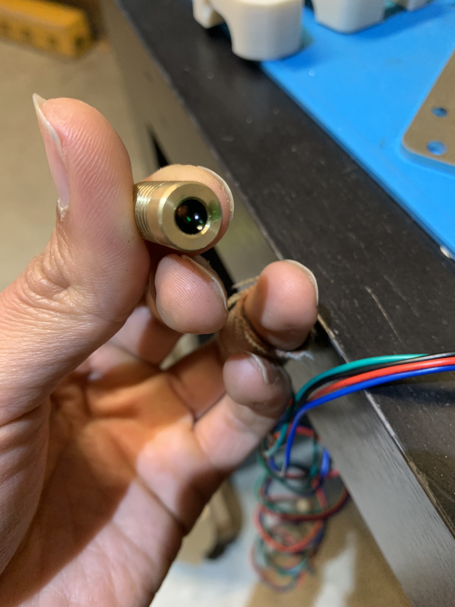
Figure 6: Worm with shaft retaining compound
Slide the worm onto the motor shaft with the hub side towards the motor. The reason we put the retaining compound on the inside of the hub side is so that it will be pushed away from the motor body during installation, preventing it from entering the motor and gumming it up. Anyway, press the worm down firmly, it should stick there in a minute or two. Wipe away any excess from the top of the worm and then set the motor on its side with the non-shaft side slightly elevated to prevent any liquid retaining compound from flowing into the motor. Leave it like that for a couple of hours for the retaining compound to harden.
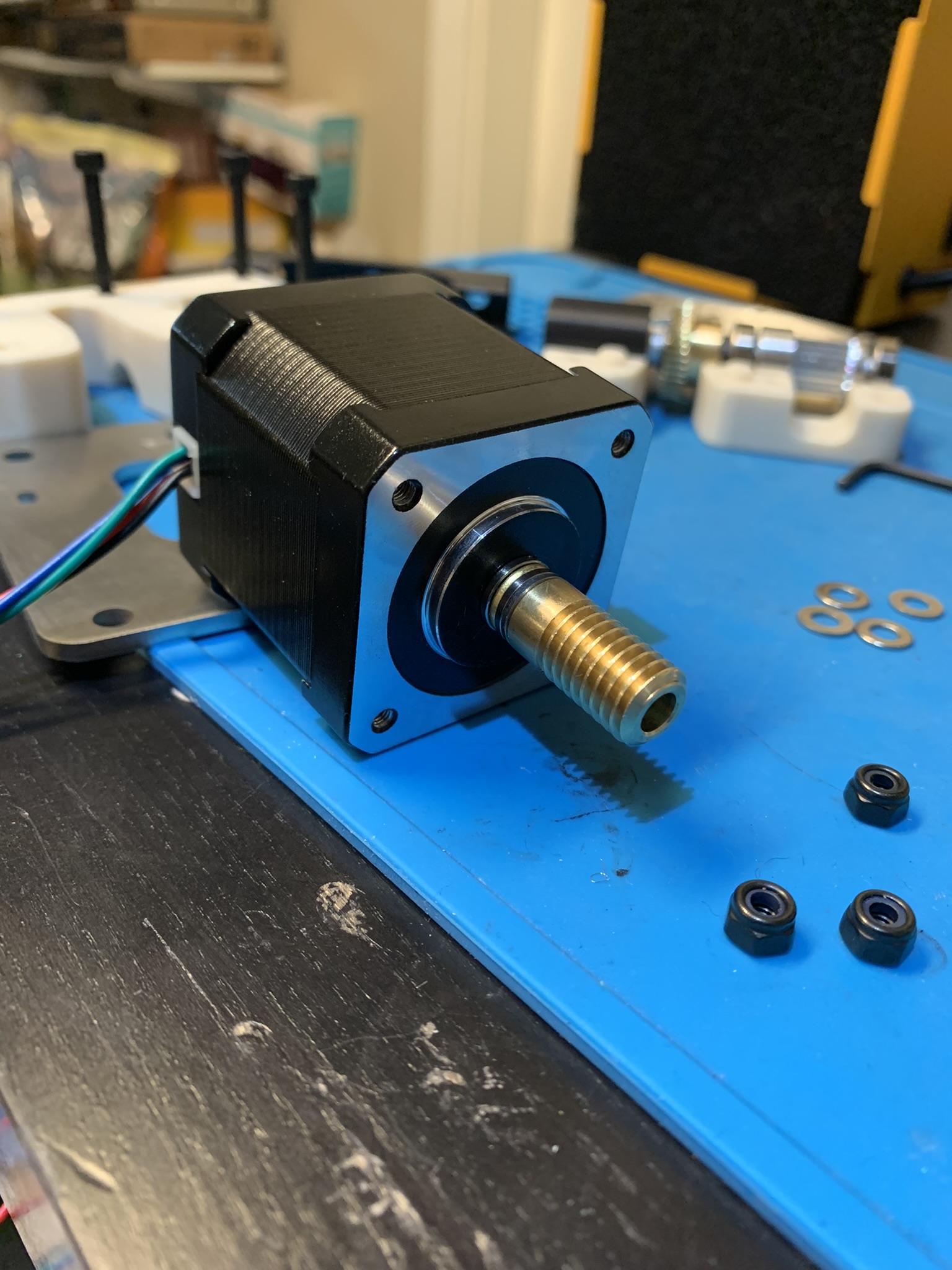
Figure 7: Motor assembly resting to dry
Optional The set screw for the worm gear sticks out quite a bit past the worm body. It should be fine, but it might collide with the plastic depending on how much the set screw sticks out and how your motor is aligned on the drive.
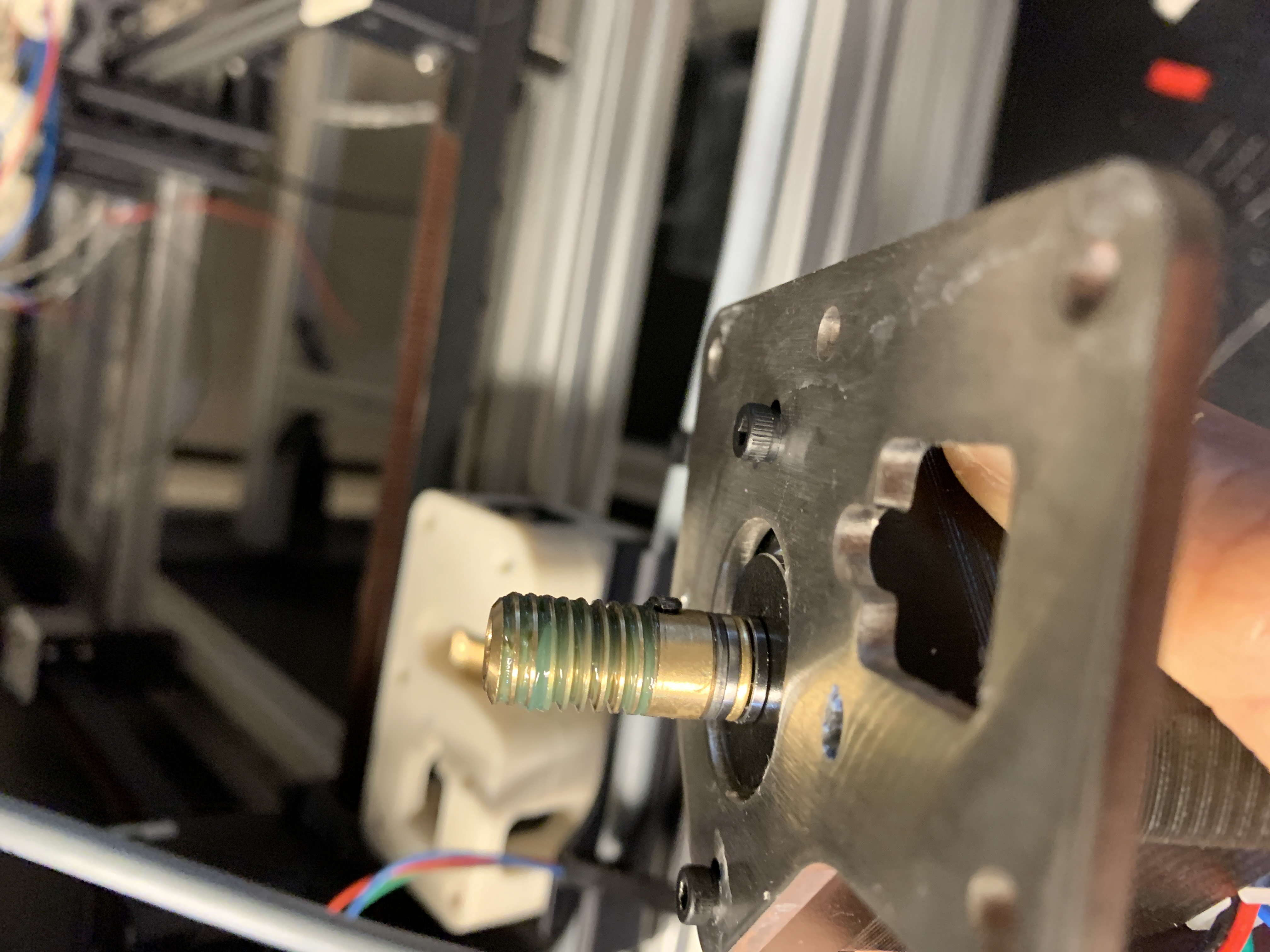
Figure 8: Set screw sticking out of the Z drive
Take a dremel to it till it’s more or less flat with the worm gear’s hub. Be very careful to not dremel the worm’s teeth.
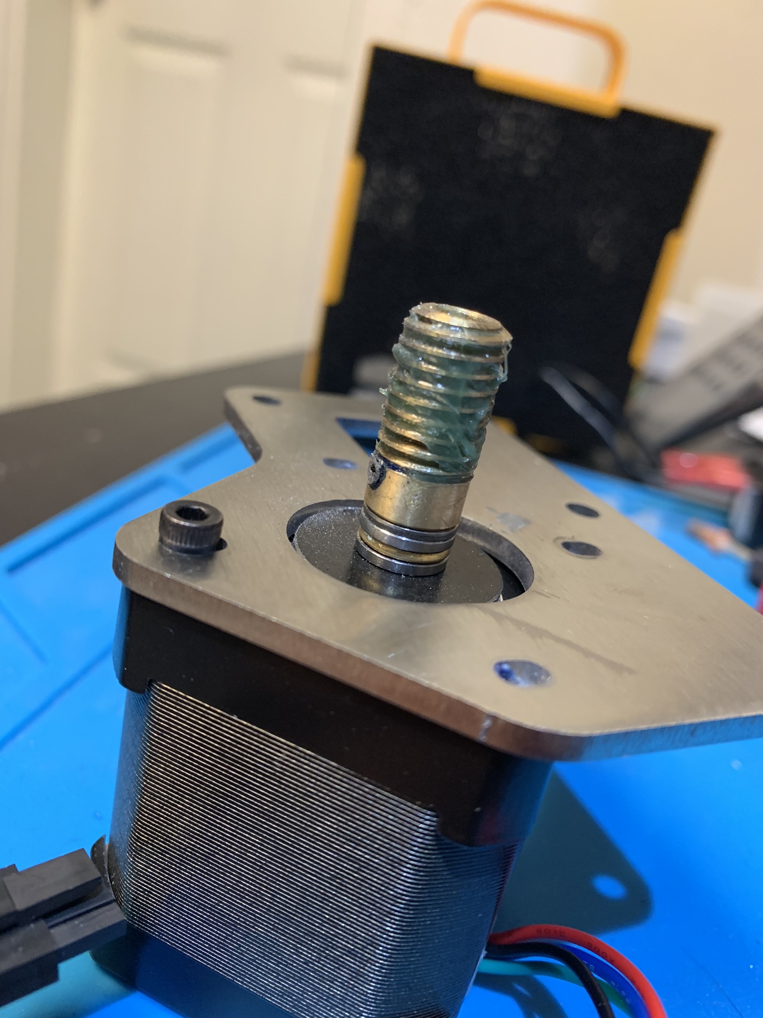
Figure 9: Set screw ground down to the worm gear’s hub
Finally, screw the steel plate onto the motor using two M3x8 SHCS. Keep both somewhat loose so that the steel plate can slide around.
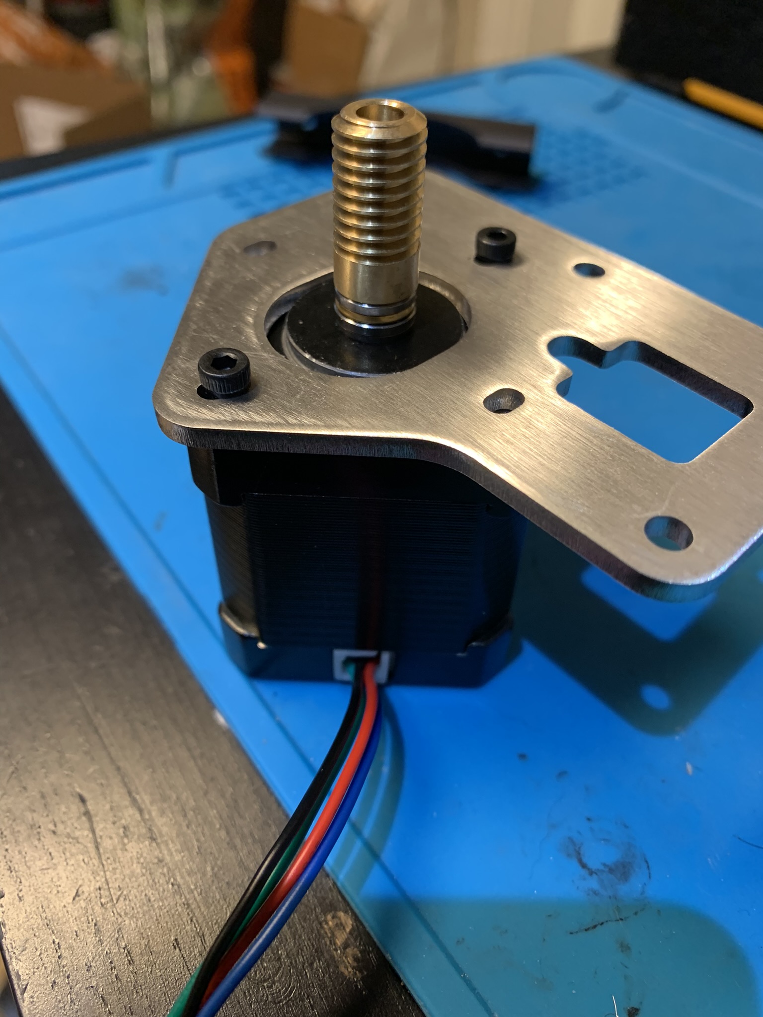
Figure 10: Motor assembly with top plate
Drive assembly
Assuming that you have a spur with a 6mm hub, take a shaft and insert
Bearing - 3mm spacer - Pulley - 1mm washer - Bearing - 3mm spacer - Spur - 3mm spacer - Bearing
Here’s what your drive shaft will look like:
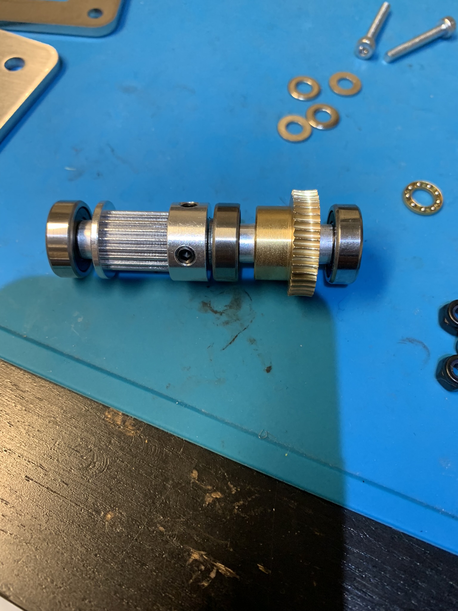
Figure 11: Drive shaft with 6 mm spur
Add the printed part onto the bearing on the spur end:
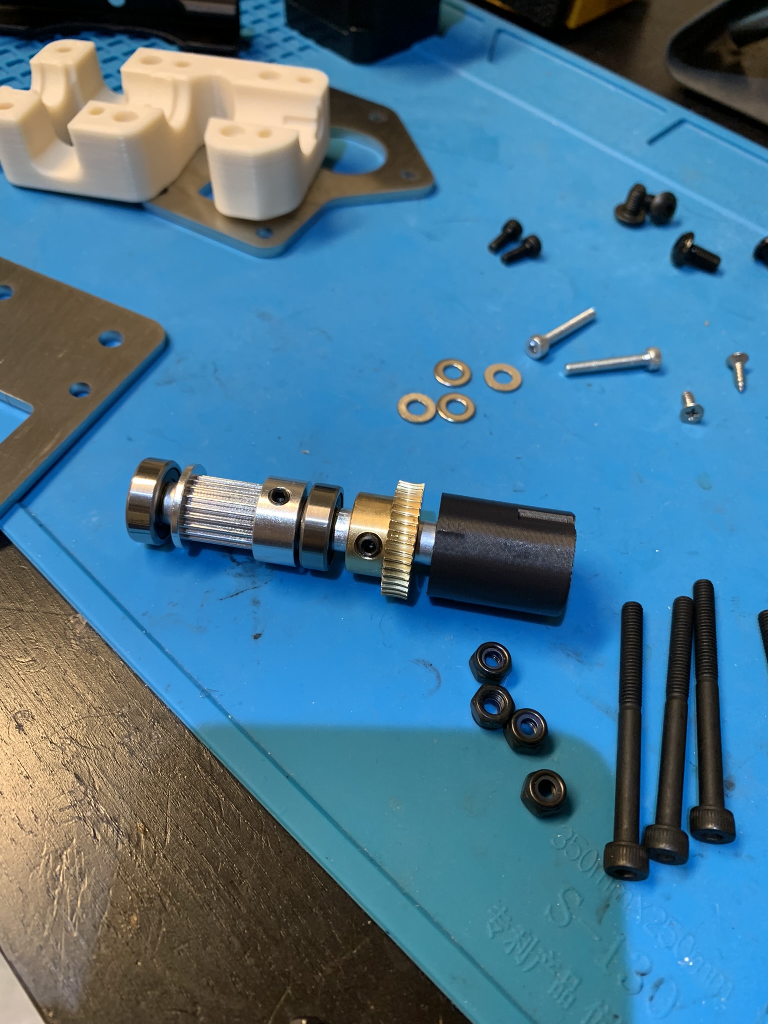
Figure 12: Drive shaft with 6 mm spur, capped
Insert the assembly into the thicker printed part. The bearings should click smoothly into place.
⚠️ This is very important - the thinner printed part should be at the bottom of the drive, and the thicker part should be on top, close to the motor. Reversing them will cause you problems. I assembled them reversed and so that’s how the pictures in this post show each drive, I fixed all four drives later once I’d discovered my mistake while testing the drives.
Update - As a result of the issues I faced with Z drive assembly, there is now a T on the top half of the Z drive. Look for the part with the T and use that here.
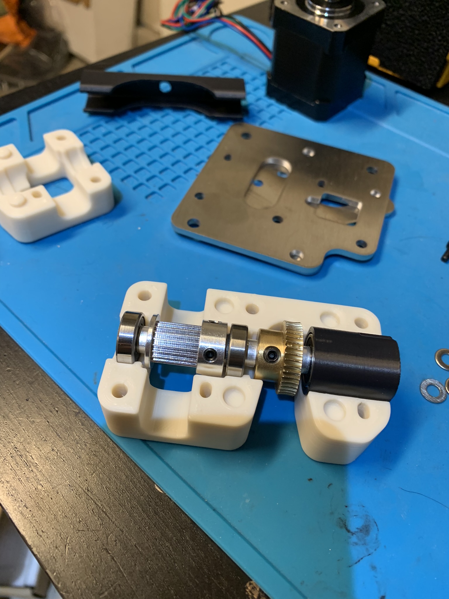
Figure 13: Drive assembly inserted into printed part
Spurs with hubs longer/shorter than 6 mm
As mentioned previously, the drive assembly is slightly different based on the length of the hub of your spur. To illustrate the need for this, here is what my assembly looked like before I fixed it:
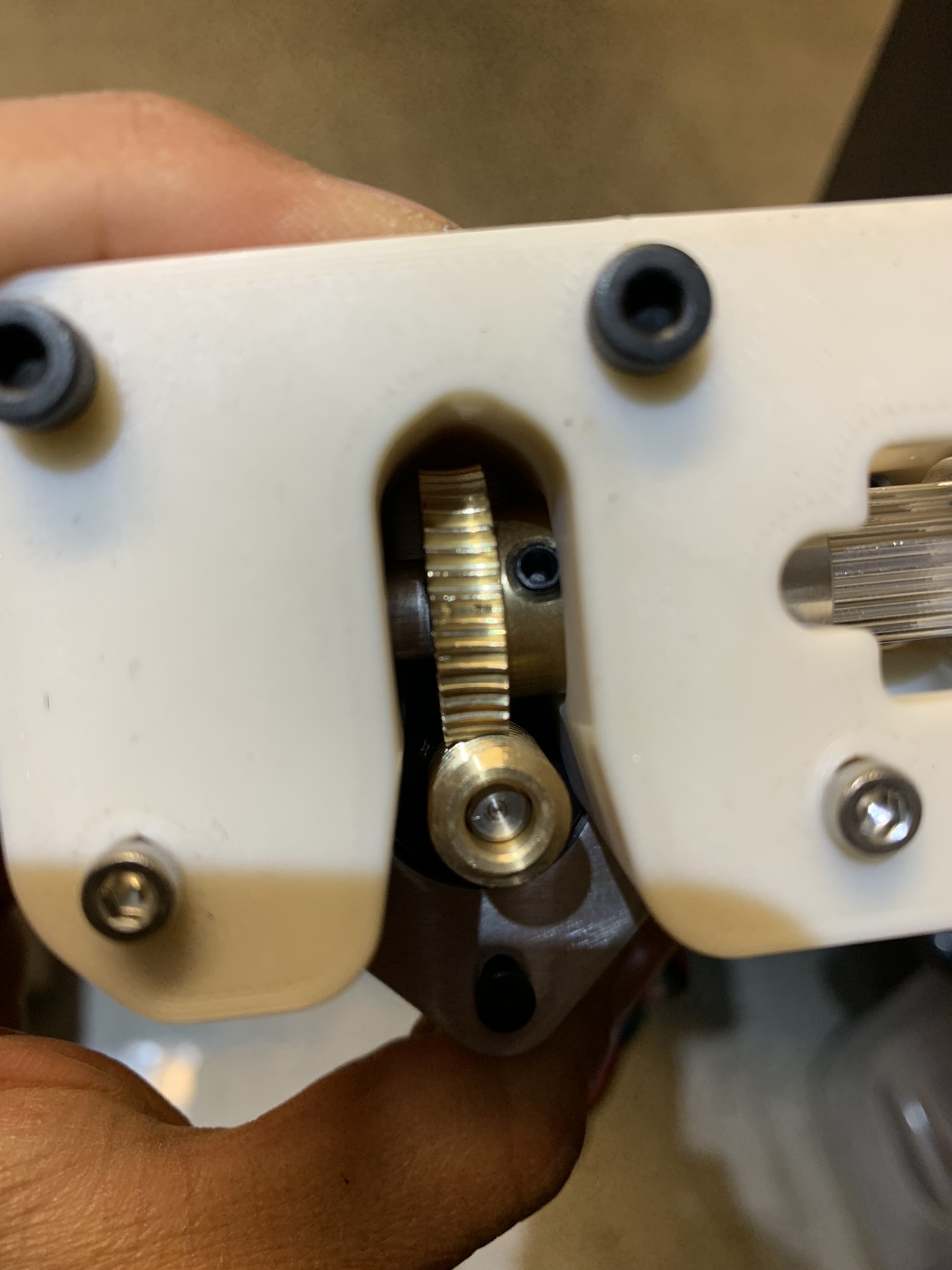
Figure 14: Drive assembly with misaligned spur
As can be seen in the picture, the spur is left of center with respect to the worm, making it so that their teeth are not fully engaged. Here’s what it looks like on the inside:
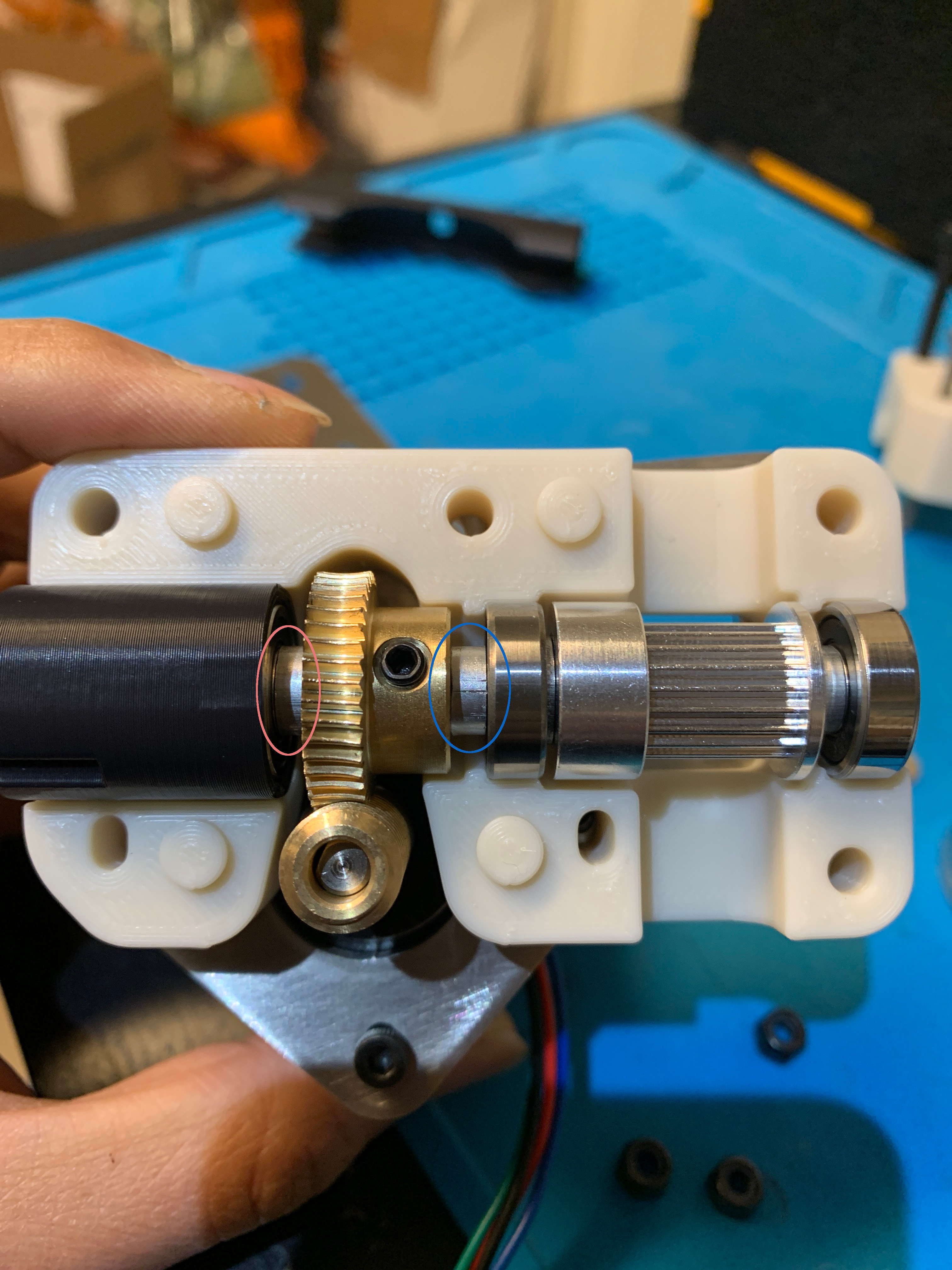
Figure 15: Drive assembly cross-section with misaligned spur
To fix this, the spur needs to move to the right, meaning the spacer highlighted in red needs to be longer and the one highlighted in blue needs to be shorter. I accomplished this by using two M5 1mm washers instead of the blue spacer and adding one M5 1mm washer between the red spacer and the spur. This fixed the alignment issue and looks like this:
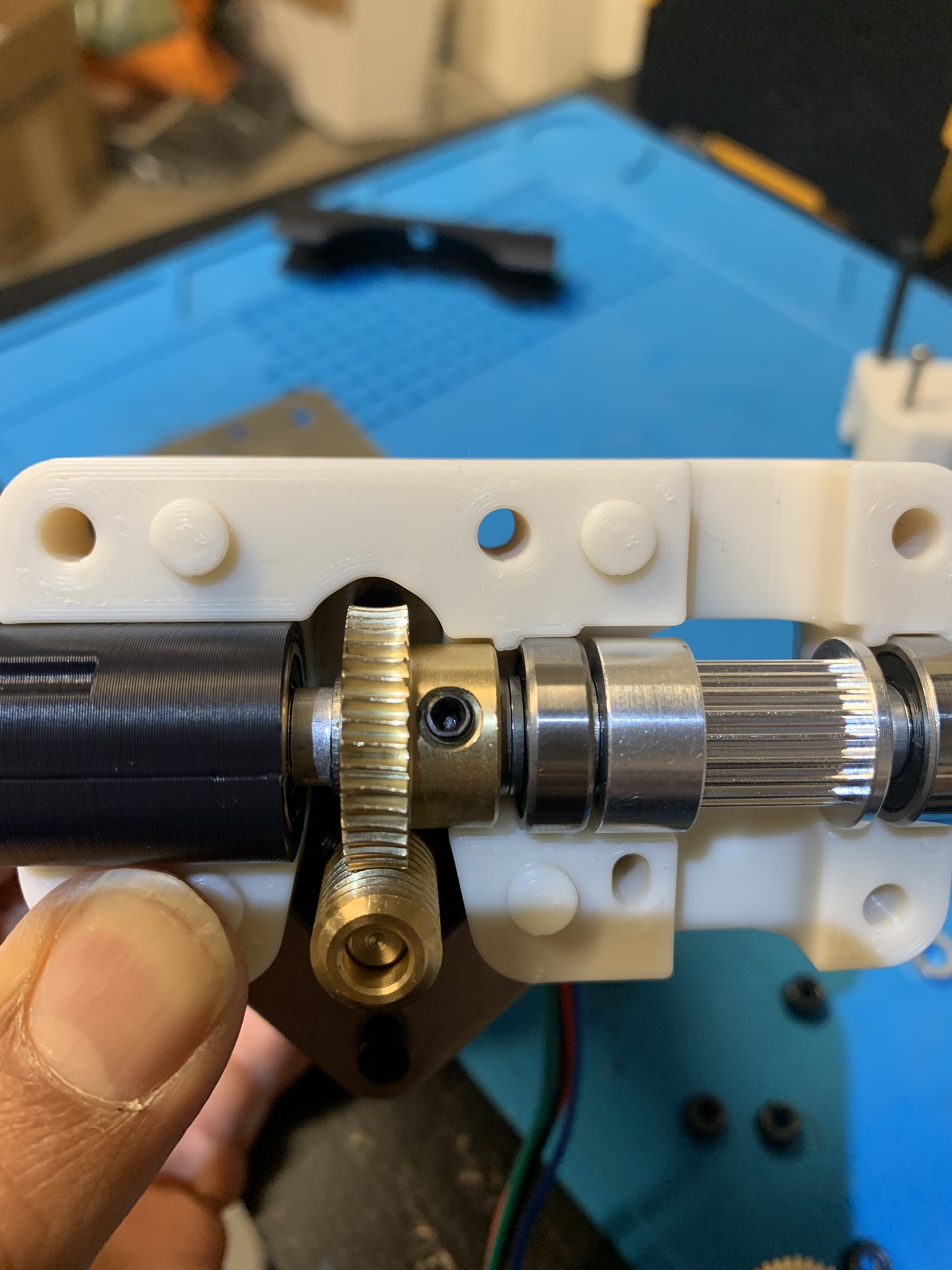
Figure 16: Drive assembly cross-section with fixed alignment
If your spur’s hub has a length different from 6mm or 7mm, you’ll have to figure out a combination of washers and spacers to align it. The toothed part of the spur should be 9mm from the bearing on its right and there should be no loose space between the spur and the bearing on the left.
Putting it together
- Stand the motor on its base.
- Place the above drive assembly around the worm so that the teeth of the worm and those of the spur mesh together. Confirm that the thicker printed part is sitting on top of the steel plate attached to the motor.
- Place the remaining (thinner) printed part on and then add the remaining steel part on top.
- Insert the four M4 bolts (with M4 washers) and two M3 bolts, and use them to align the whole thing. The steel part will move around a bit, align it manually so that it’s centered on the rest of the assembly.
Once everything is aligned, slide the motor and steel plate around until you can see that the worm-spur teeth are fully engaged. It should look like this:
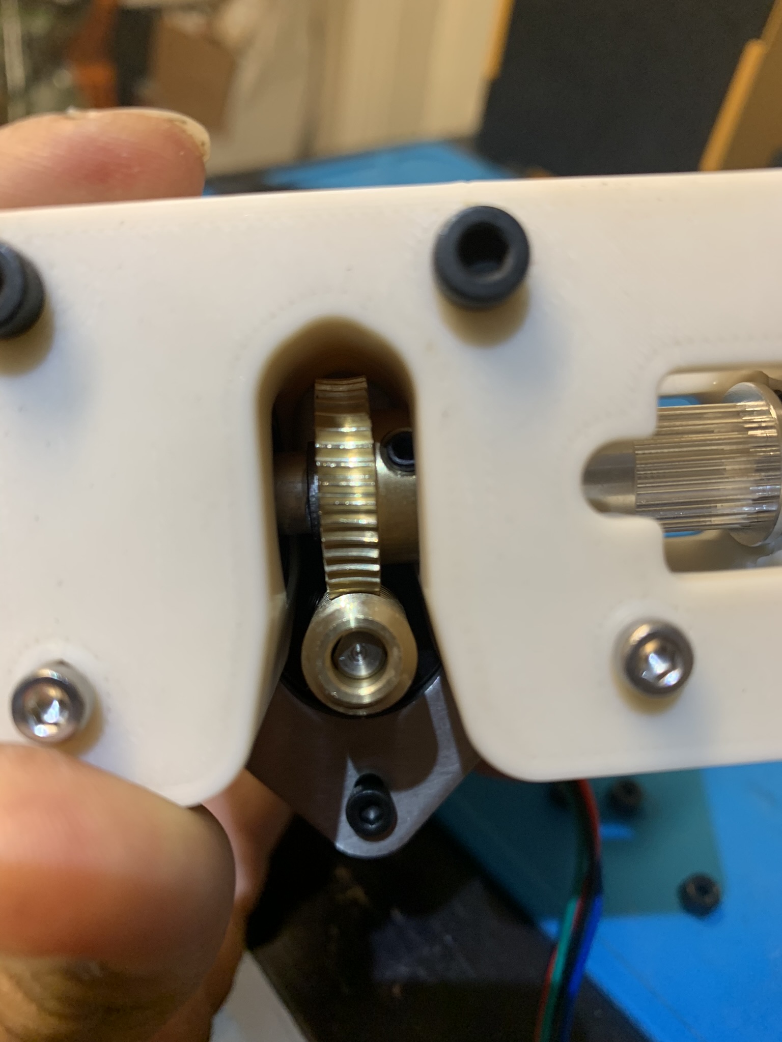
Figure 17: Drive assembly with fixed alignment and worm
Try to push on the spur’s teeth with a fingernail or blade and confirm that it doesn’t budge. Tighten the bolt I’m pointing at in the picture below:
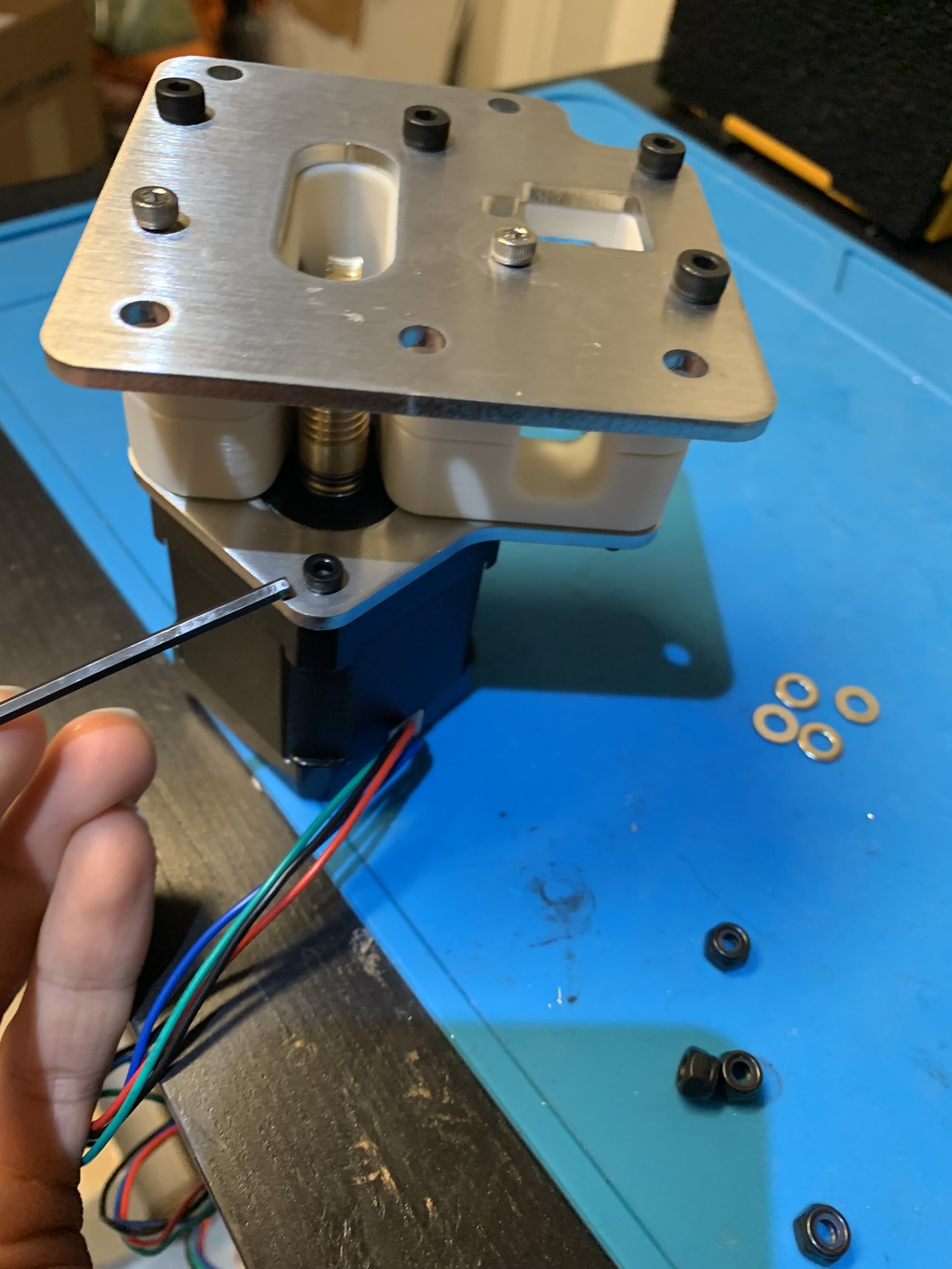
Figure 18: Bolt that should be tightened to secure motor to plate
Now pull out the motor and the plate attached to it from the rest of the assembly and remove the other M3x8 bolt holding the plate to the motor. This bolt cannot be accessed when the drive is assembled, so we’re going to skip it.
Next, we need to grease the worm gear. This doesn’t need to be fancy: I took a dollop of grease on my finger tip and rubbed it into the teeth of the worm as uniformly as I could. Excess grease is fine, just try to not have giant blobs of grease hanging off the sides of the worm.
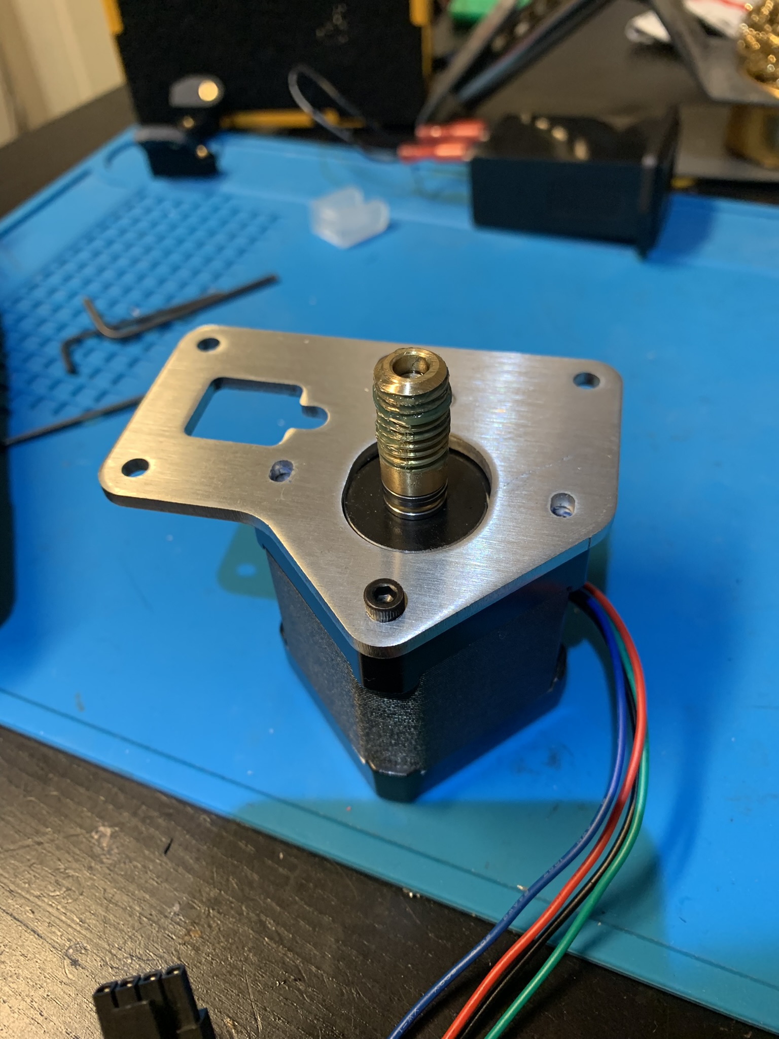
Figure 19: Motor assembly resting to dry
Finally, put the assembly back together the same as you did before and tighten all bolts. The bottom steel plate will move a bit: there’s no good way to align it perfectly, so just try and eyeball it so that all edges look centered. Insert the two self-tapping screws into the grooves in the main-color and accent parts.
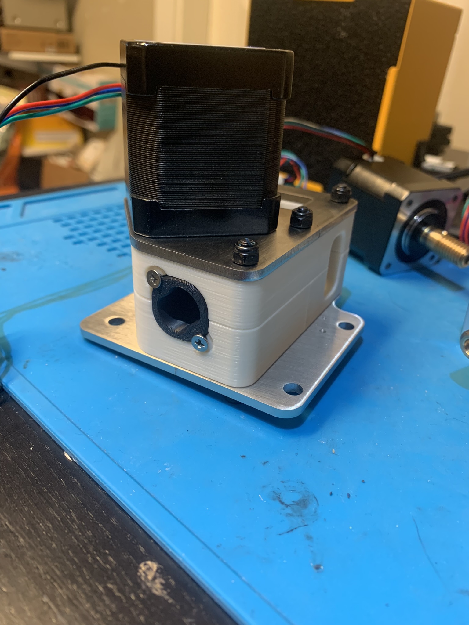
Figure 20: Fully assembled Z drive
Installation
Insert roll-in nuts into your frame’s extrusions. Pay attention to the one nearest the internal bracket: align it so that the hole is towards the bracket.
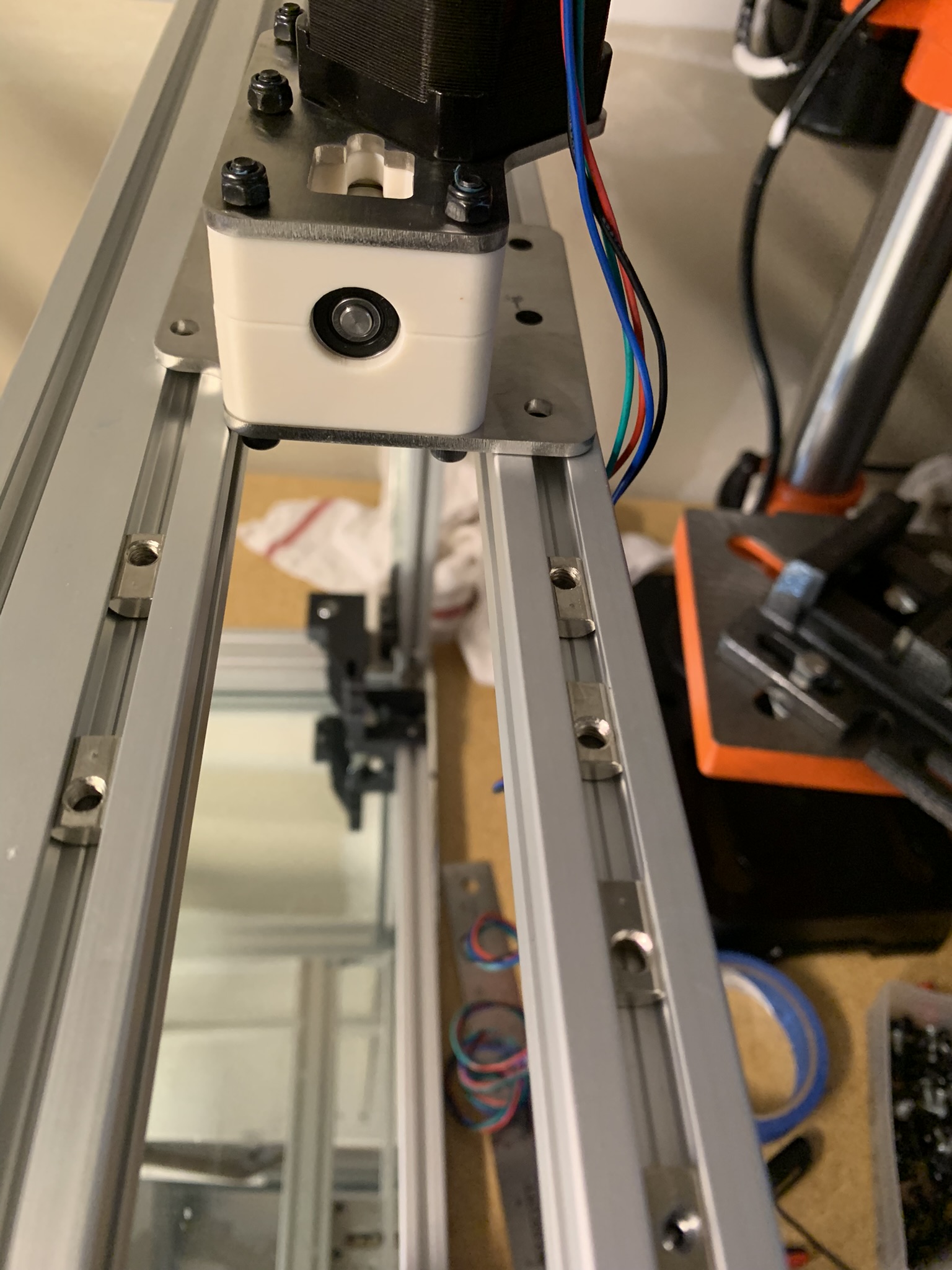
Figure 21: Roll-in nuts installed
Place the finished assembly on your frame’s extrusions. Using a pair of calipers, position the drive 20.35mm from the end of the extrusion. Use a flat object to ensure that the right edge of the bottom steel plate is coplanar with the right extrusion. Use two M5x8 bolts and fasten the left side. Place the printed part and use three M5x10 bolts to fasten the right side. Note that you might have to adjust the exact position of the drive based on whether the belts stay centered once you’ve moved the bed up and down a bit.
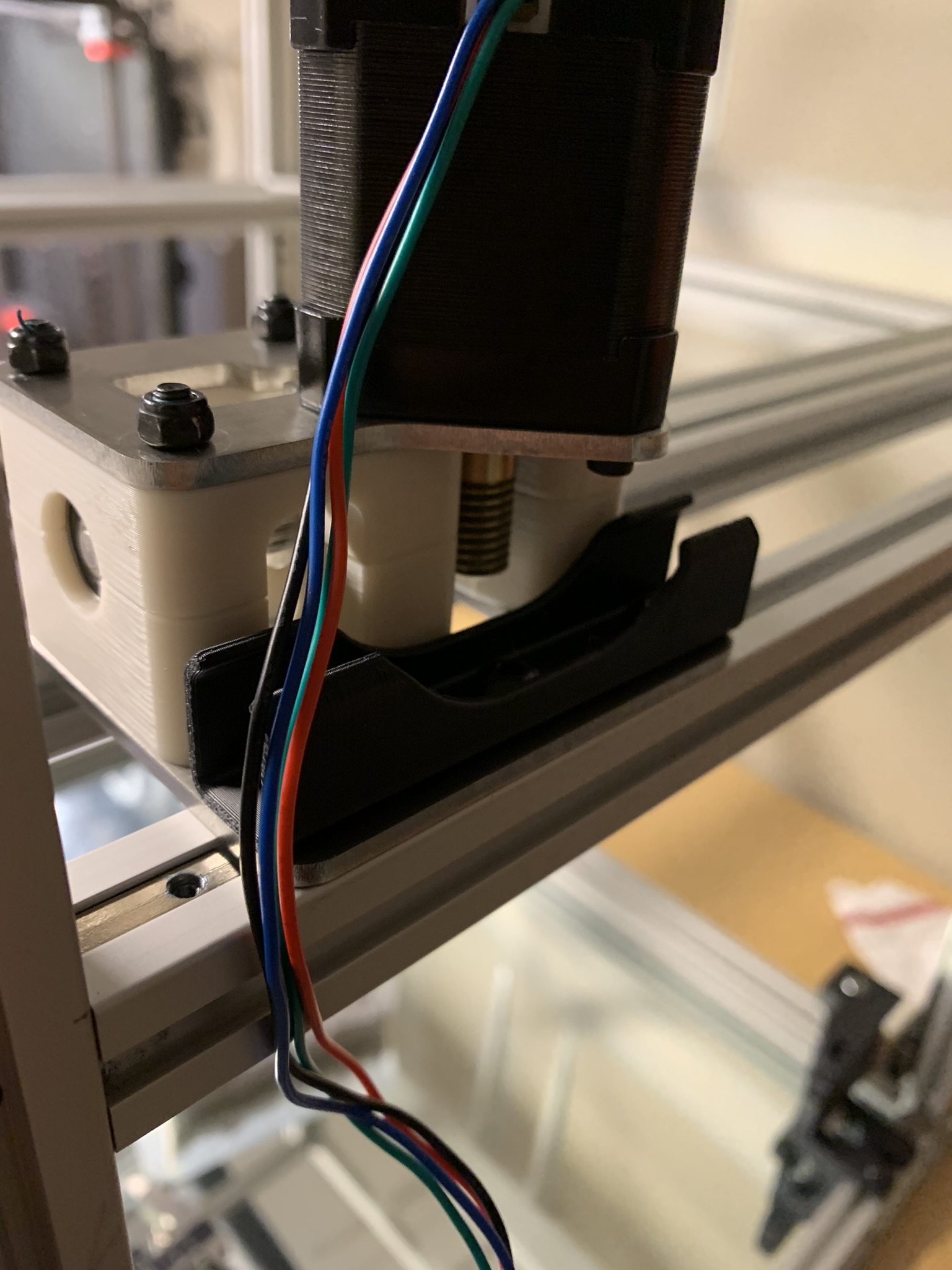
Figure 22: Roll-in nuts installed
Repeat the above process for the remaining three drives. The drive we just assembled can go on the front right or back left; the front left and back right are mirrored.