K2 Build Log Part One: Frame
Mar 1, 2022After sourcing all the parts for an Annex K2 Summit Edition, I finally started building it. I’m documenting my build process here along with pitfalls I ran into and how I overcame them.
Preparing the extrusions
I chose to get unprepared extrusions, so I had to drill and tap them myself. The printer’s repository has STLs with jigs and fixtures for drilling if you’re using a hand drill. I used a cheap drill press that I bought for this purpose, so I didn’t end up using any of the printed jigs. The drilled holes can be 6-8 mm in diameter. Misumi’s pre-drilled extrusions come with 8 mm holes, I used a 6 mm drill bit since it’s easier. The main thing to note here is to double-check holes before drilling them. I drilled one hole 5 mm off and then had to drill the right one overlapping with the incorrect one.
While tapping, go slow. One turn in and half turn back. Make sure you use enough lubricant, I used Tap Magic Aluminum.
Assembling the frame
This is arguably one of - if not the most - important part of the assembly. If your frame is not “square” (aka all corners perpendicular) you’ll run into unpredictable issues during assembly or while printing. Take as much time here as is necessary. It took me two days (off and on).
The frame can be assembled in multiple ways, I chose to assemble the front and back faces first. I used a 1-2-3 square and a mirror to assemble the front and back faces as rectangular as possible. I then attached the top and bottom extrusions to the back face and finally slid the front face onto it. Don’t forget to add internal right-angle brackets, you’ll use all 20 of them. Don’t forget to slide ALL of the gantry extrusions in during assembly, I forgot some and had to take half the printer apart to slide them in. Lightly tighten the bolts of the inner extrusions with them in roughly the right positions.
After assembling each face check that:
- Opposite sides are parallel. Verify this by measuring the distance between sides at each end.
- Diagonals are equal. Verify this by measuring the distance between opposite corners.
Both are necessary. If sides are parallel but diagonals are not equal, you’ll have a parallelogram. If sides are not parallel but diagonals are equal, you’ll have a rhombus. You need a rectangle. You might need to adjust extrusions by sliding one side up or down to make diagonals equal, this is fine. However, leave one side - either top or bottom - fixed and slide extrusions around only on the other side. I chose to have the top be fixed since the gantry sits close to the top. Here’s one of the bottom corners that I had to adjust in such a fashion.
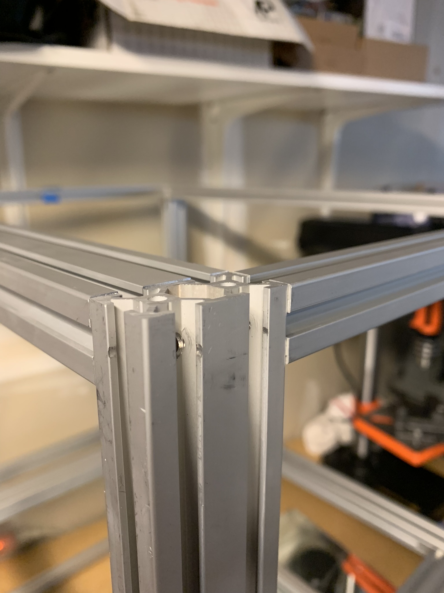
Figure 1: K2 corner with extrusions not flat
A good enough frame is one with all opposite sides parallel and all face diagonals within 1 mm of each other.
Face is a parallelogram
If you find that one of the faces is a parallelogram (meaning sides are parallel but the diagonals are not equal), you need to force it into a rectangular shape. Check all four corners of the face using a 1-2-3 square. You’ll likely find that two of the angles are less than 90 degrees and the remaining two are more than 90. The way to fix this is by laying that face on a flat surface, loosening all four bolts holding that face together and using a 1-2-3 square on one corner at a time. Pick a corner, use the square to align the extrusions so that they are perpendicular to each other and slowly tighten the bolt(s) in that joint. Once the bolt starts getting tight, stop and confirm that the joint is still perpendicular before tightening it further.
One additional gotcha that might affect you (it impacted me) is that one of your extrusions might not have a flat cut, meaning that the surface of the end of the extrusion isn’t perpendicular to the sides of the extrusion. If you find that one of your faces is a parallelogram no matter what you do, this might be why. You can debug it by trying to tighten the joints in different orders until you find the joint that is problematic. Tighten all other joints first and then the problematic one.
Assembling the gantry
With a square frame, assembling the gantry is easy. I positioned each extrusion 21.5 cm from the top extrusion of that face (with the printer upside down for ease of assembly). To aid with this, I drew marks on the sides of the vertical extrusions at a distance of 21.5 cm. For example:
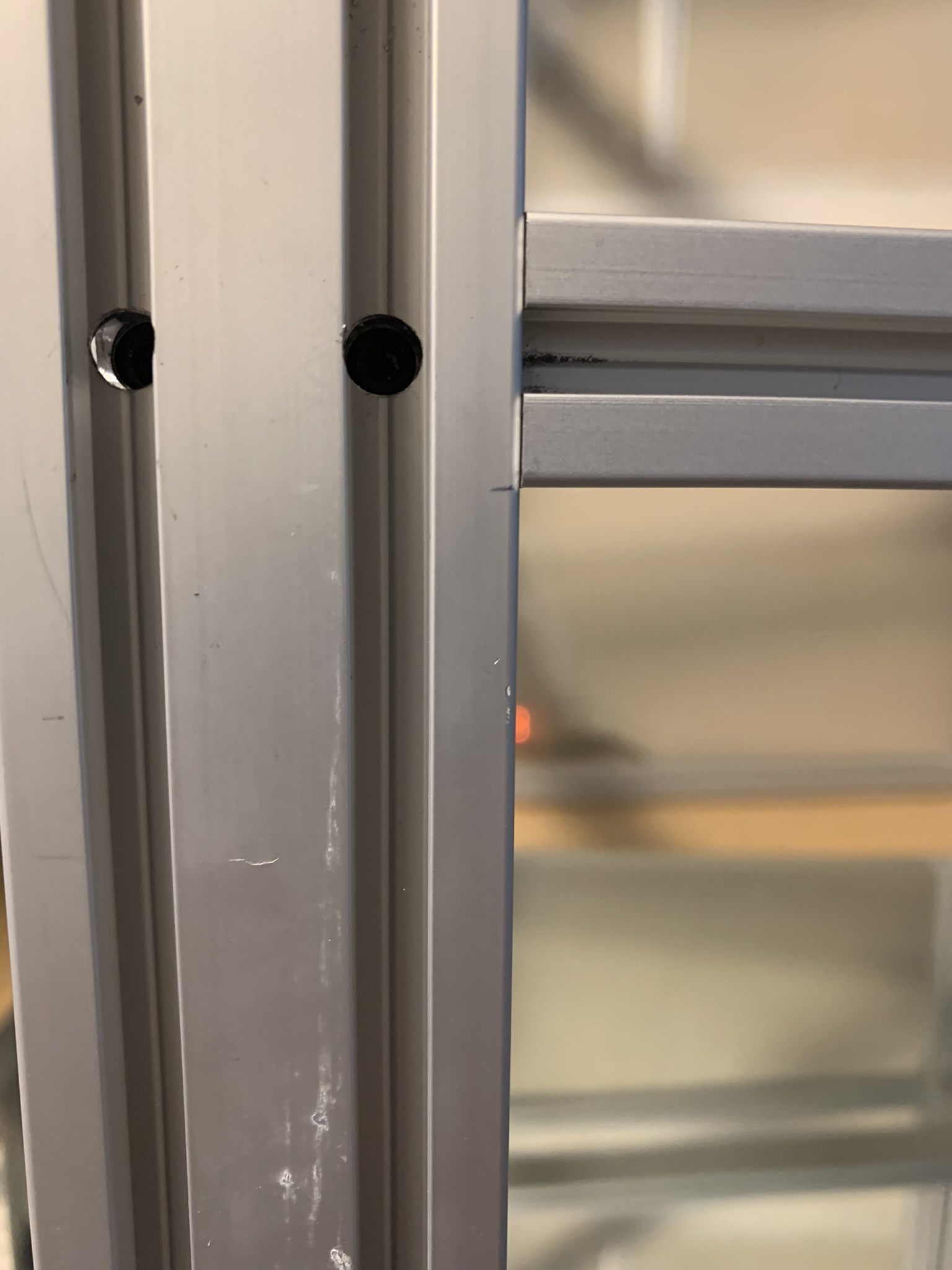
Figure 2: K2 gantry height
Start with one of the 2040 extrusions and use a 1-2-3 square to align it at the right height, perpendicular to the vertical extrusion and parallel to the horizonal extrusion (the top one in my case). Then move on to the adjacent 2020 extrusions, align it at the right height and use the square to make it coplanar with the 2040 extrusion you just tightened. Then move on to the remaining 2040 and 2020 extrusions.
To align the two inner gantry extrusions, I used a pair of calipers to position them 45 mm from the gantry’s side 2020 extrusion. I then used a 1-2-3 square to make it planar with one of the adjacent gantry extrusions and tightened both bolts. Repeat for the other inner extrusion.
If you have trouble with the inner extrusions, you can use a jig I made. Print two and use two M3x12 bolts and roll-in nuts each to secure them to the front/back extrusions, then simply press the inner extrusion against them.
Last steps
Tighten the grub screws for all internal brackets and you’re done with the frame!
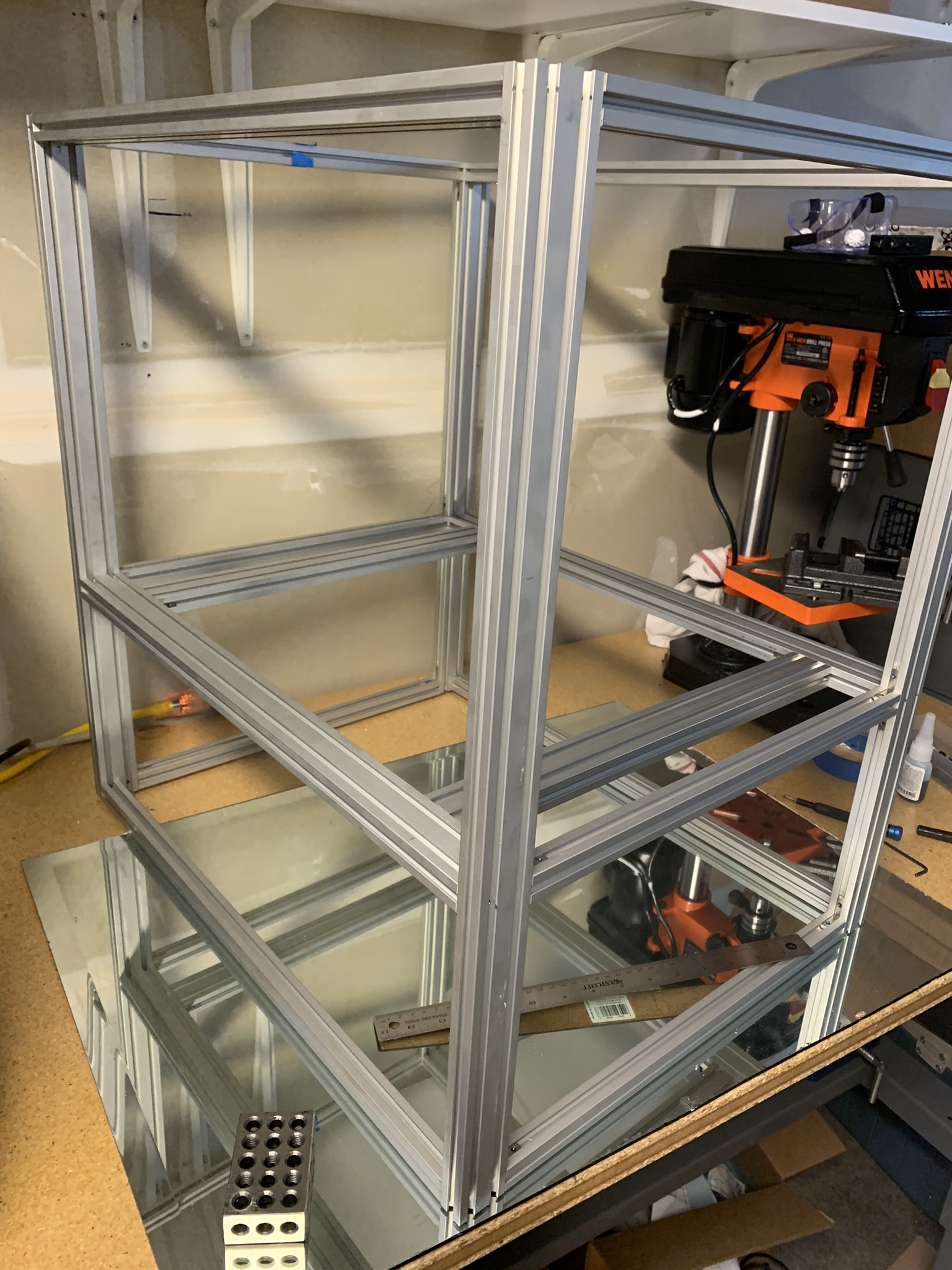
Figure 3: K2 gantry height