K2 Build Log Part Eight: Toolhead and Extruder
Mar 30, 2022For the toolhead, you have a choice of extruders and hotends. I chose to use a Mosquito (clone) and Sherpa Mini. I also chose to use the (optional, but strongly recommended IMO) Mosquito Net to keep your hotend rigid.
Toolhead heatsets
Insert tall M3 heatset inserts into the holes shown below:
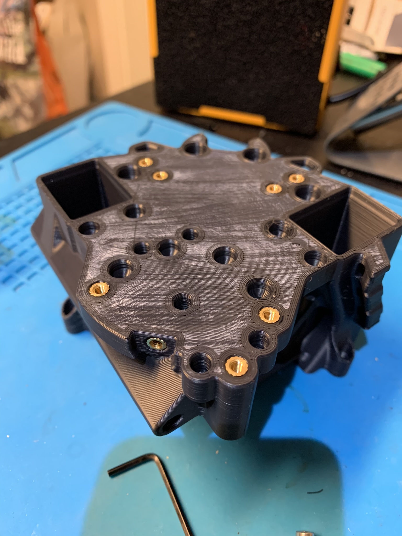
Figure 1: Heatset inserts for top side of the toolhead
If you’re using the mosquito net, insert tall M3 heatset inserts into the bottom of the part:
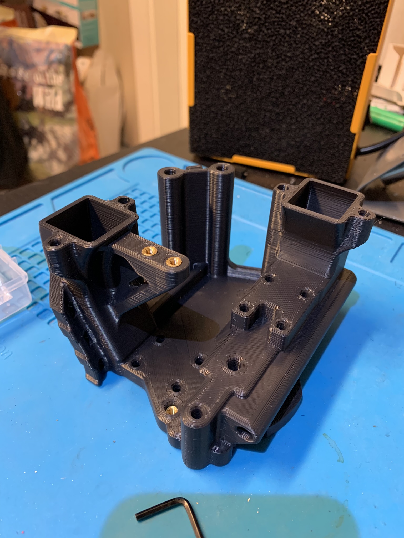
Figure 2: Heatset inserts for bottom side of the toolhead
Hotend
As stated at the beginning, I’m using a mosquito clone, but the instructions should be adaptable to your hotend of choice.
Attaching the tool mount
Put some loctite into the top mounting holes of the mosquito.
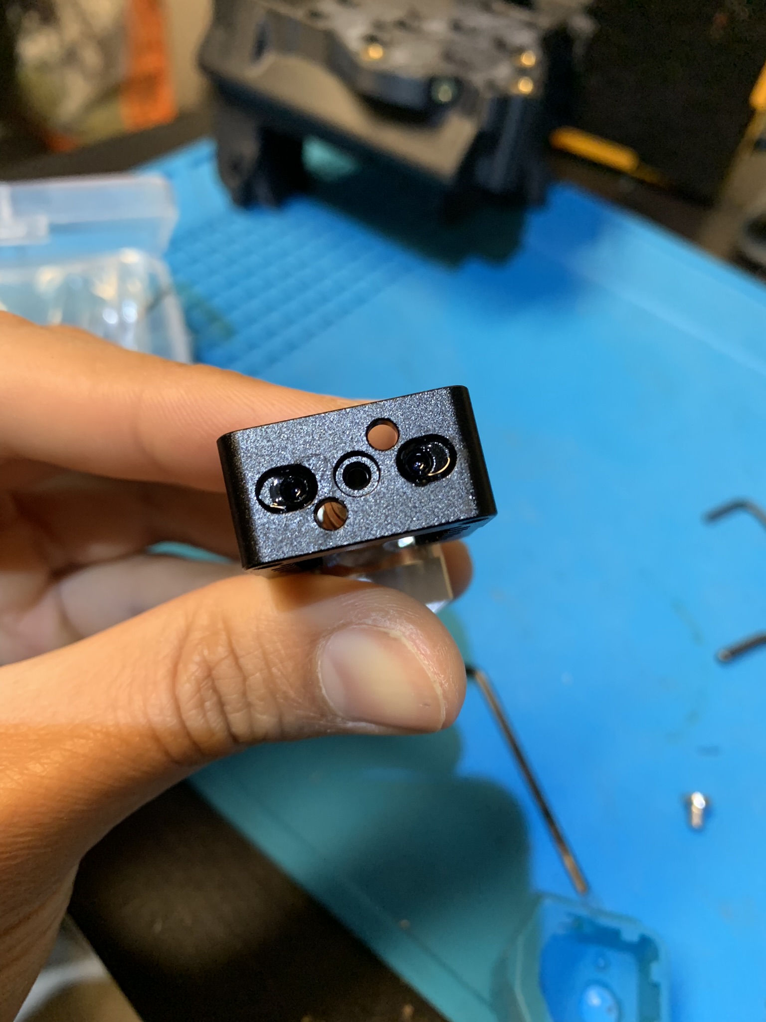
Figure 3: Loctite inside mosquito’s mounting holes
Place the tool mount on top and attach it to the mosquito with M2.5x16 bolts.
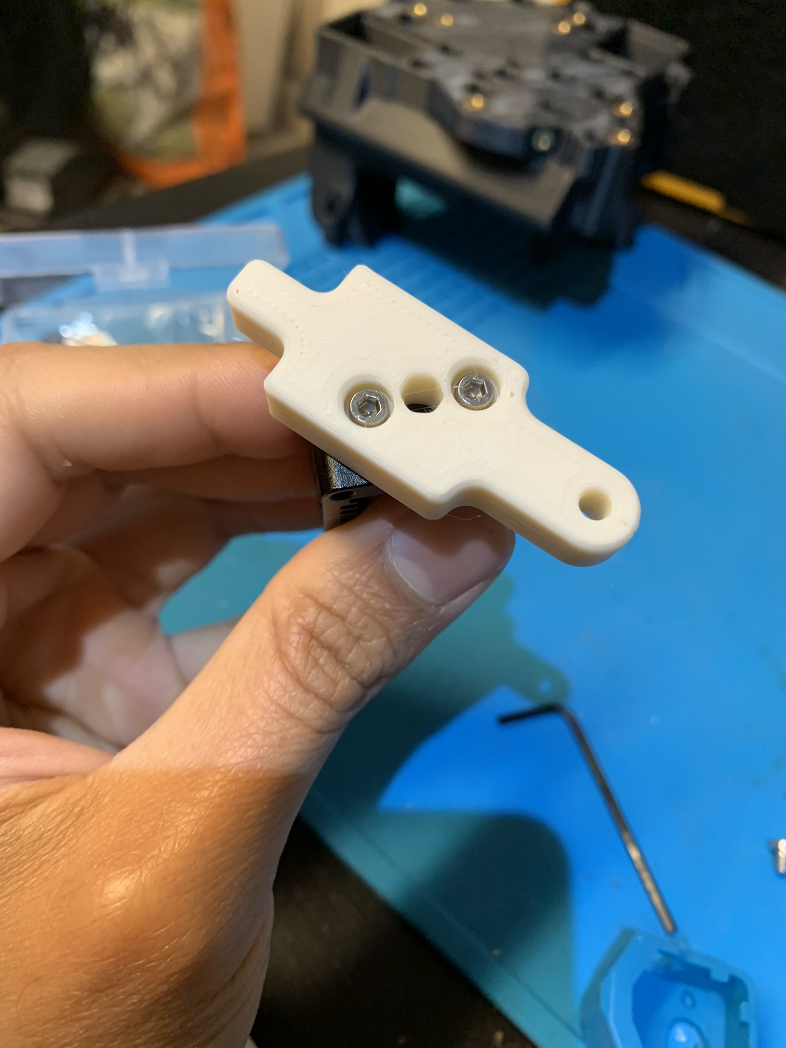
Figure 4: Mosquito tool mount attached
Optional: Installing the mosquito net
Slice has extremely precise tolerances for their hotends, but the clones don’t. We need to make sure the mosquito net attaches to the hotend correctly. Place the net on the bottom of your toolhead and bolt it in using 2x M3x8 BHCS.
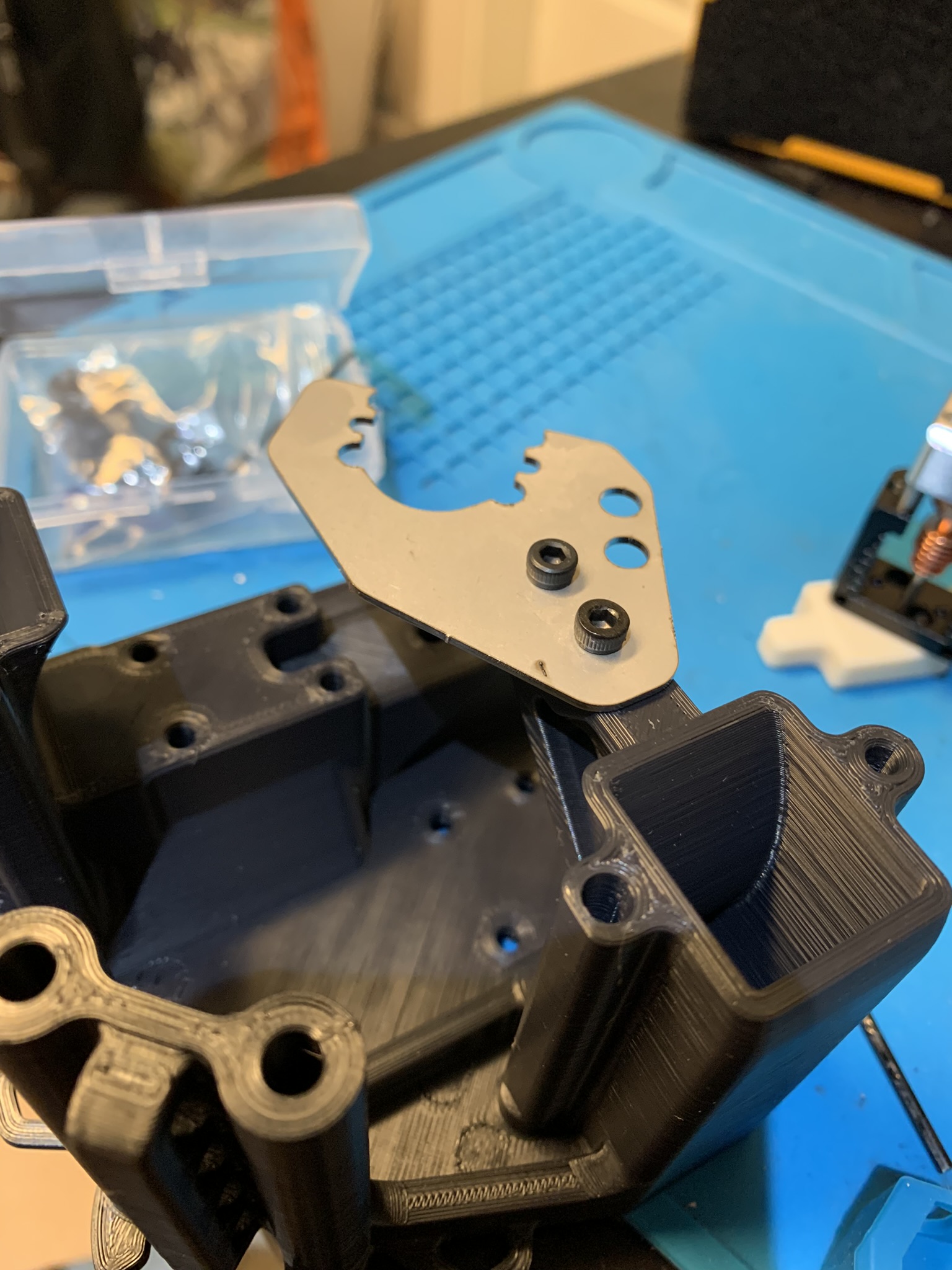
Figure 5: Mosquito net attached to toolhead
Slide your hotend into place as shown in the picture below.
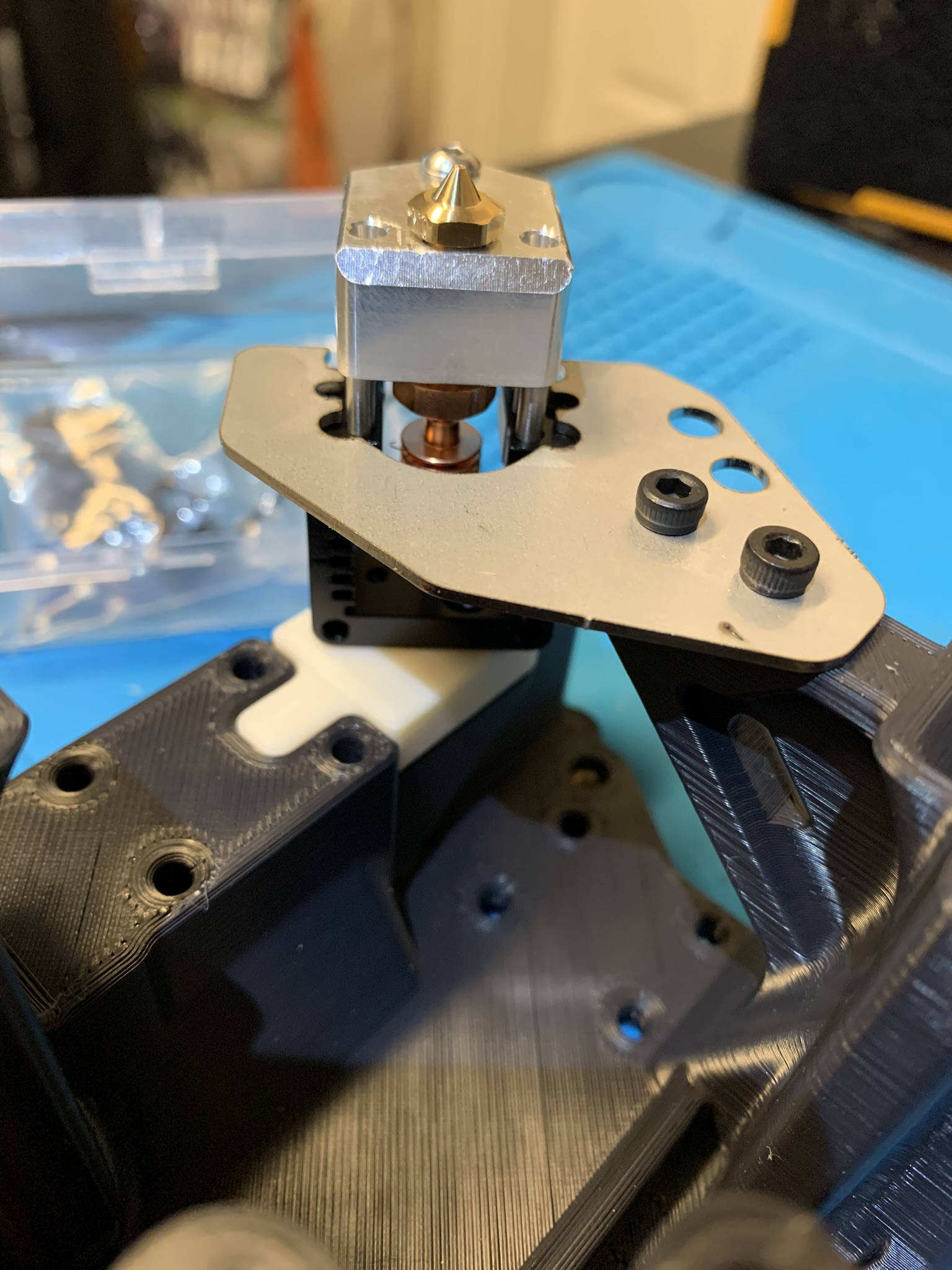
Figure 6: Mosquito net test fit, placed onto toolhead
Take a look at it from the side. The tool mount should be flush with the toolhead, and the net should ideally be flush with the heatsink of your hotend. If that’s not the case, there should at least be enough room between the net and the heater block for the hotend sock to fit. If the net doesn’t lie flush with your hotend’s heatsink, you’ll have to use nuts or shims between the net and the heatsink in the next step.
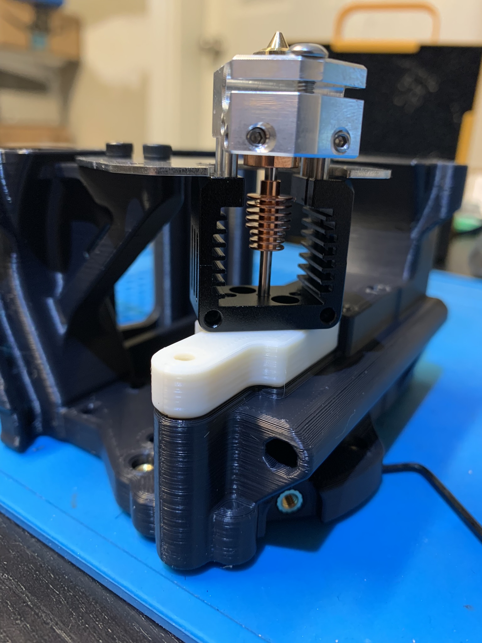
Figure 7: Mosquito net test fit check
Remove the two bolts attaching the heater block to the heatsink.
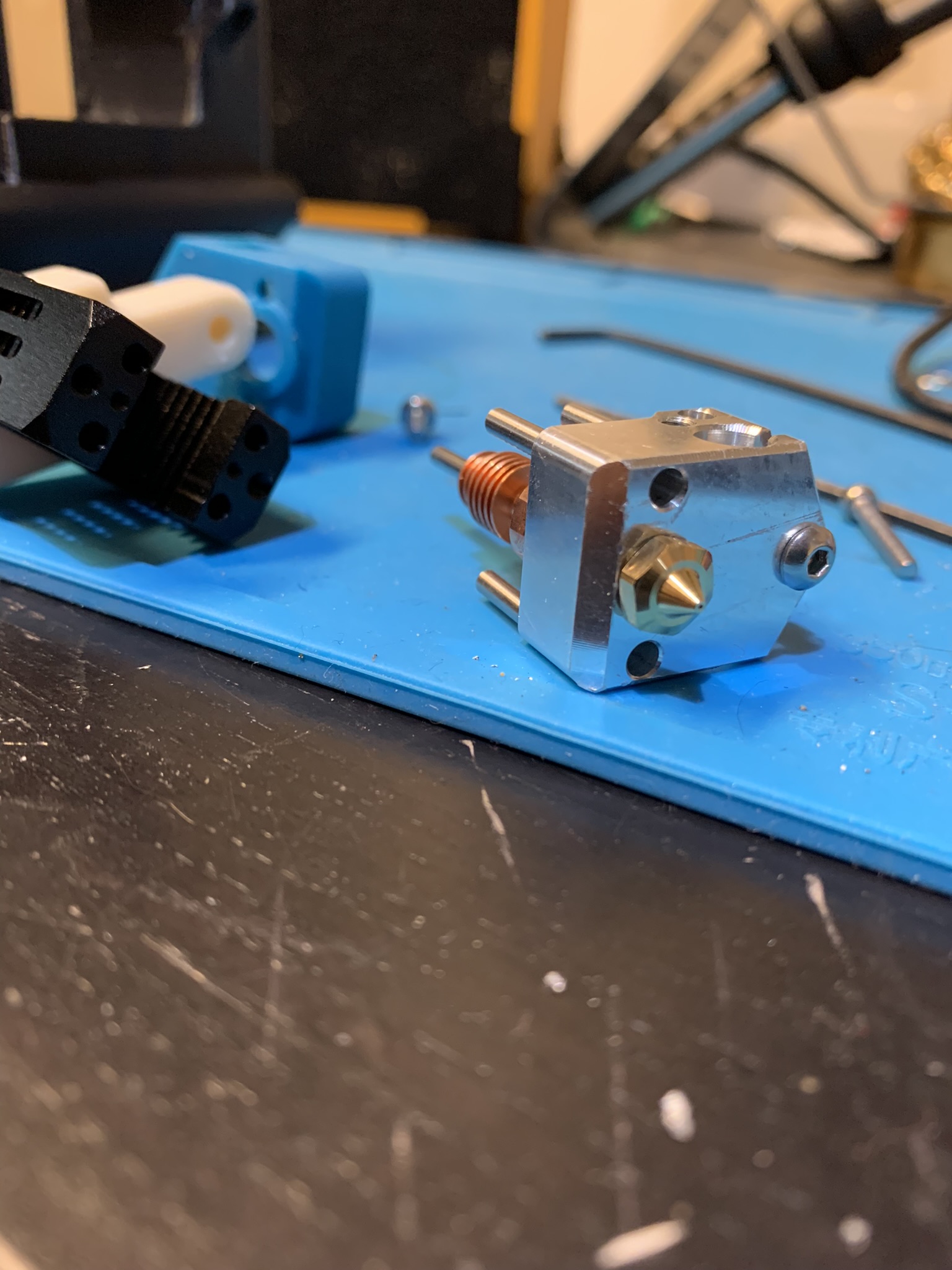
Figure 8: Mosquito with heater block removed
Place the net flush against the heatsink (or use shims/nuts if you need to) and attach it securely to the heatsink using 2x M2.5x8 bolts.
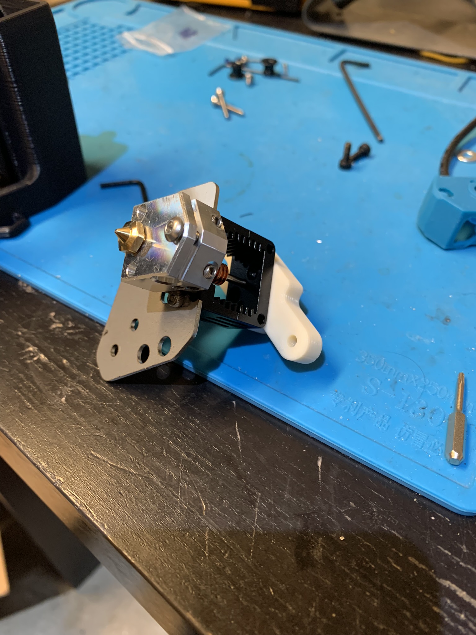
Figure 9: Mosquito net attached to heatsink
Hotend wiring
- If you aren’t using a mosquito net, just run your wires out the right side of the heater block.
- If you are using a mosquito net, your hotend wiring will necessarily be a little awkward. Run them out the left side of your heater block and up and over the net. I tried a number of other configurations that didn’t work:
- Wires coming out the right doesn’t work because they hit the tensioner at max X
- Wires going under the net doesn’t work because they get in the way of the fan ducts
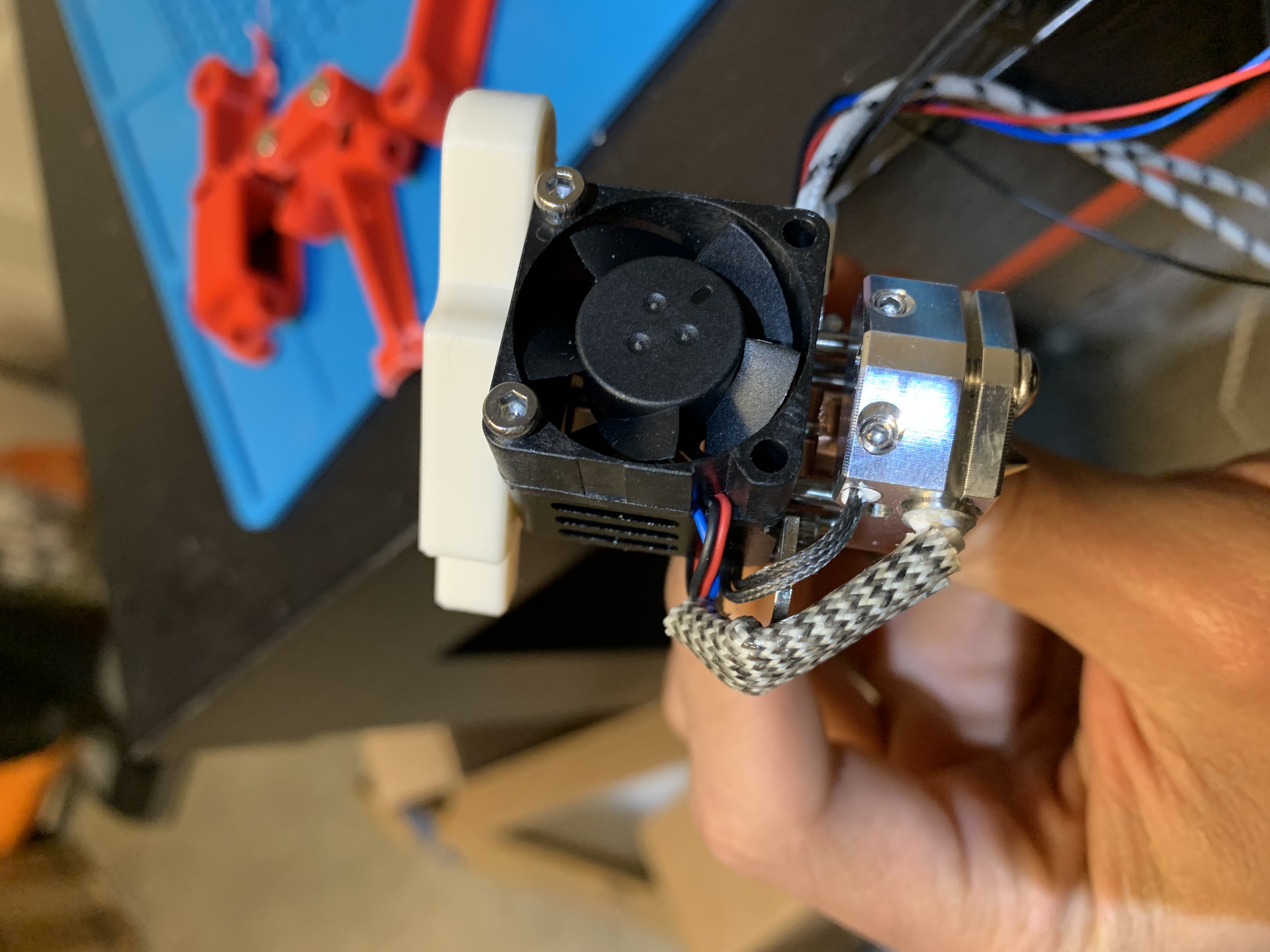
Figure 10: Hotend wiring with mosquito net, front view
Use a zip tie to attach your wires to the net

Figure 11: Hotend wiring with mosquito net, lower view with zip tie
Toolhead installation
Bring your Y cross rail carriage to the front and X cross rail carriage to the right. To install the toolhead, you’ll have to tilt it slightly to pass the cross extrusion through the protruding part
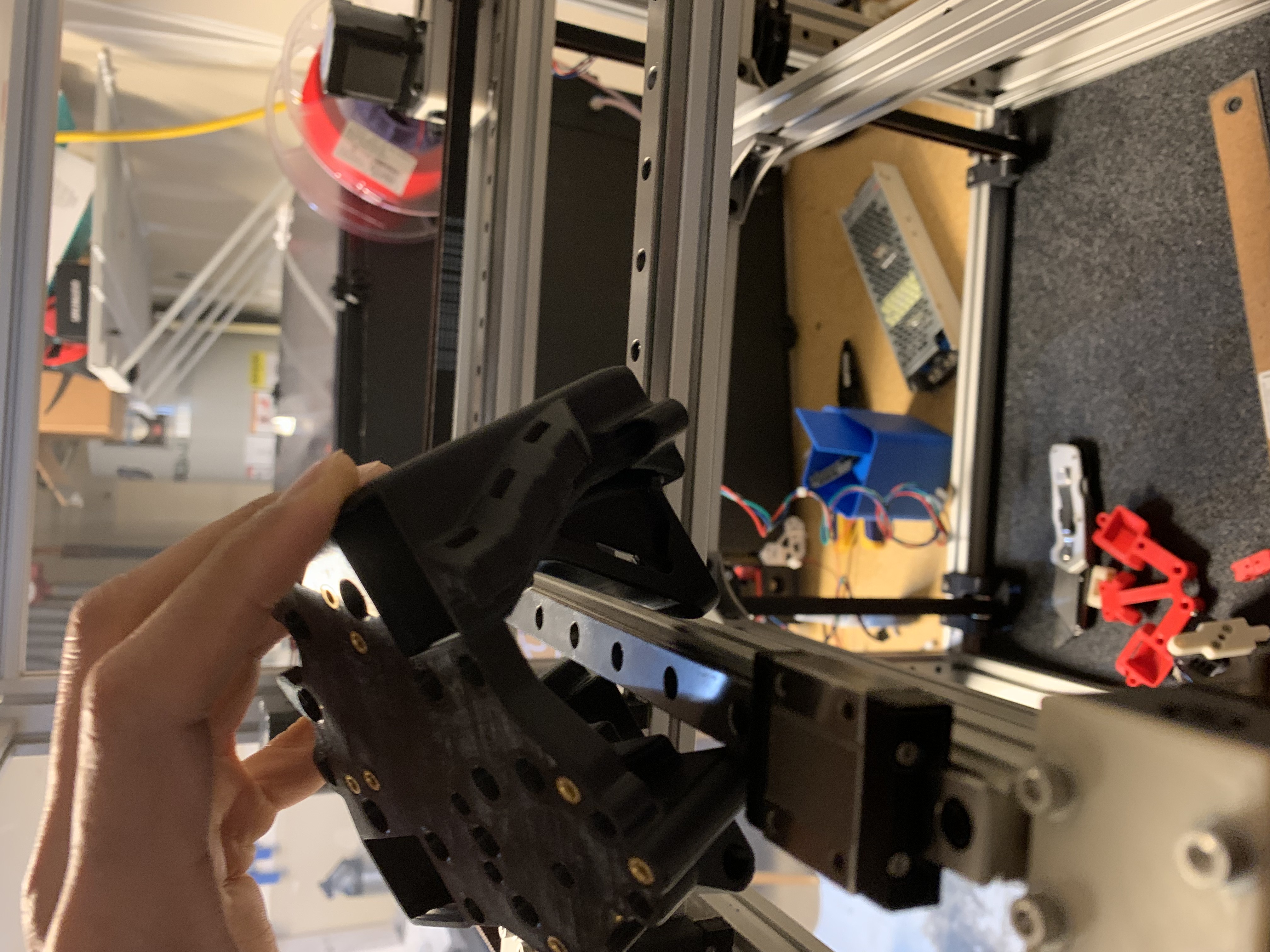
Figure 12: Toolhead installation, alignment
Slide the carriages into place and rest the toolhead on them.
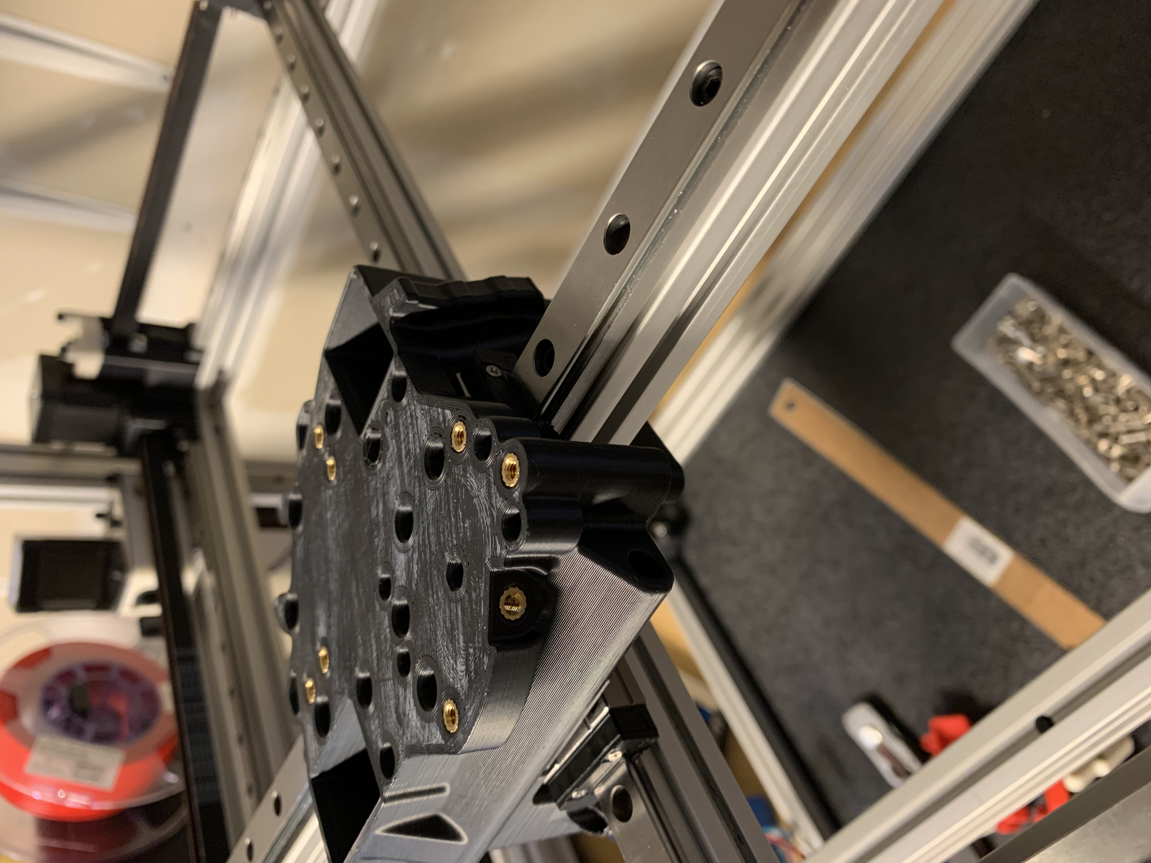
Figure 13: Toolhead installation, placement
Loosely attach the toolhead to the X cross rail carriage using 4x M3x8 SHCS
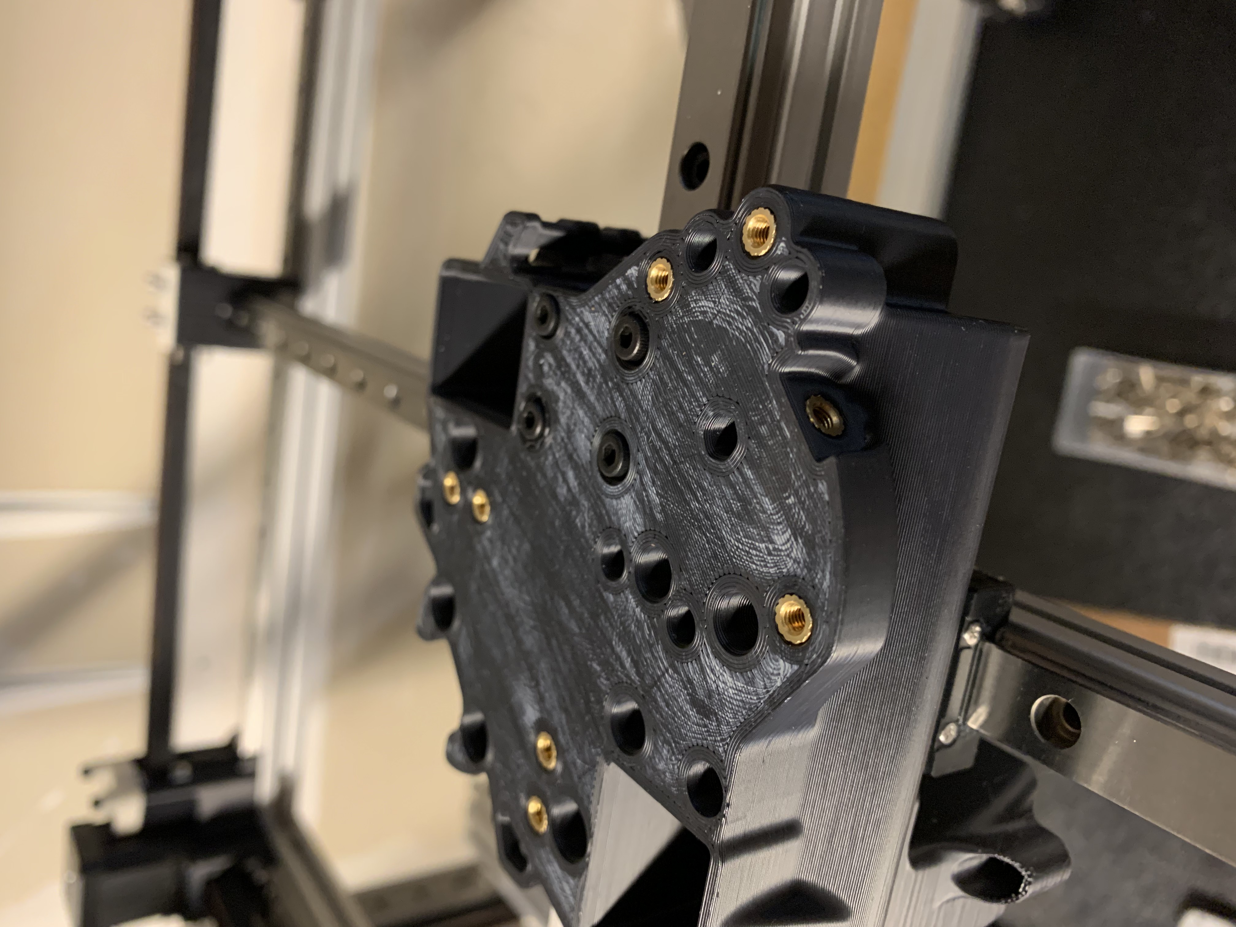
Figure 14: Toolhead installation, X cross rail carriage bolts
Slide the nub of your hotend mount into the groove in the toolhead, between the printed part and the Y cross rail carriage
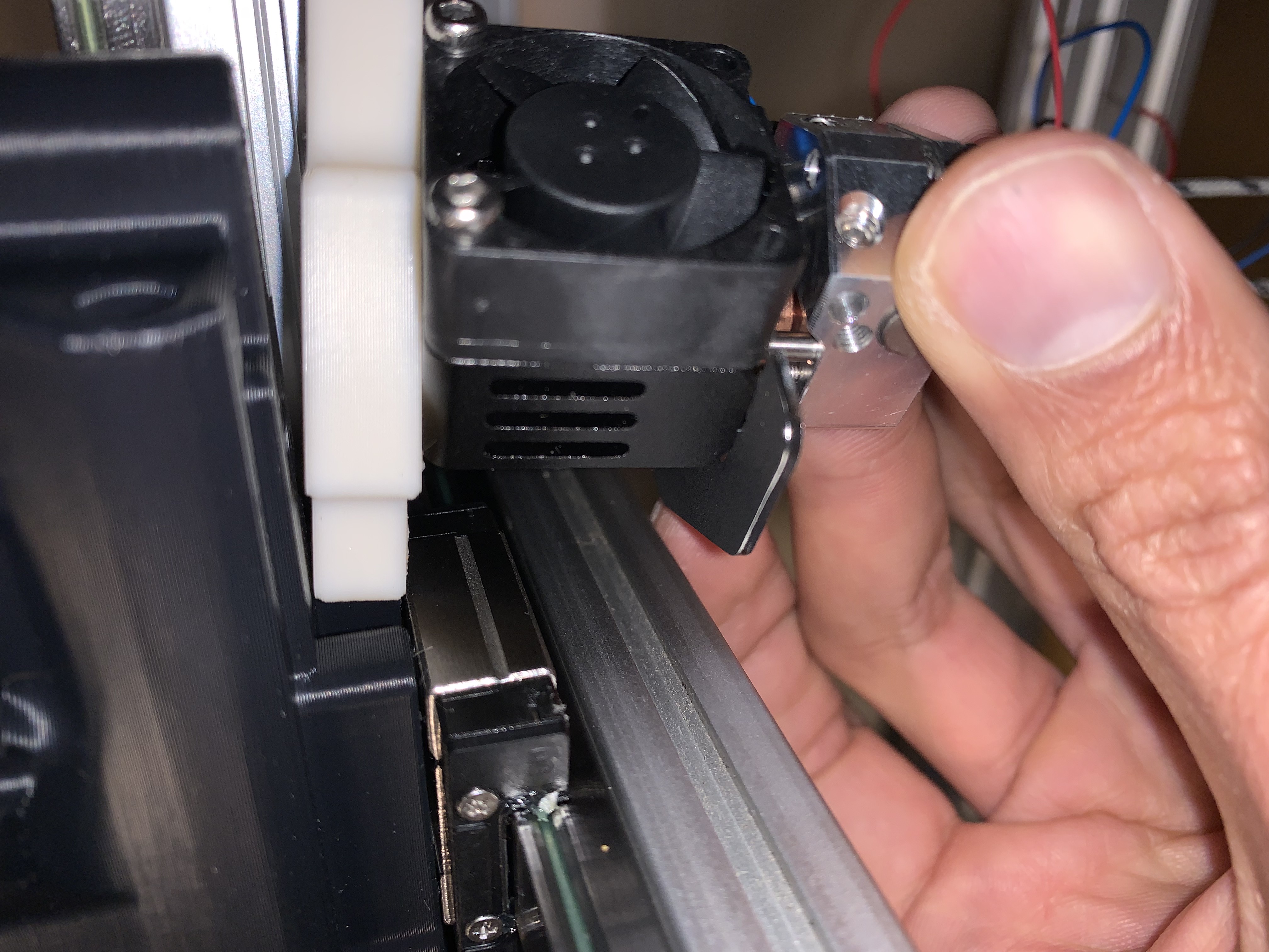
Figure 15: Tool installation, slide into place
Bolt the tool mount to the toolhead using an M3x35 SHCS, use loctite.
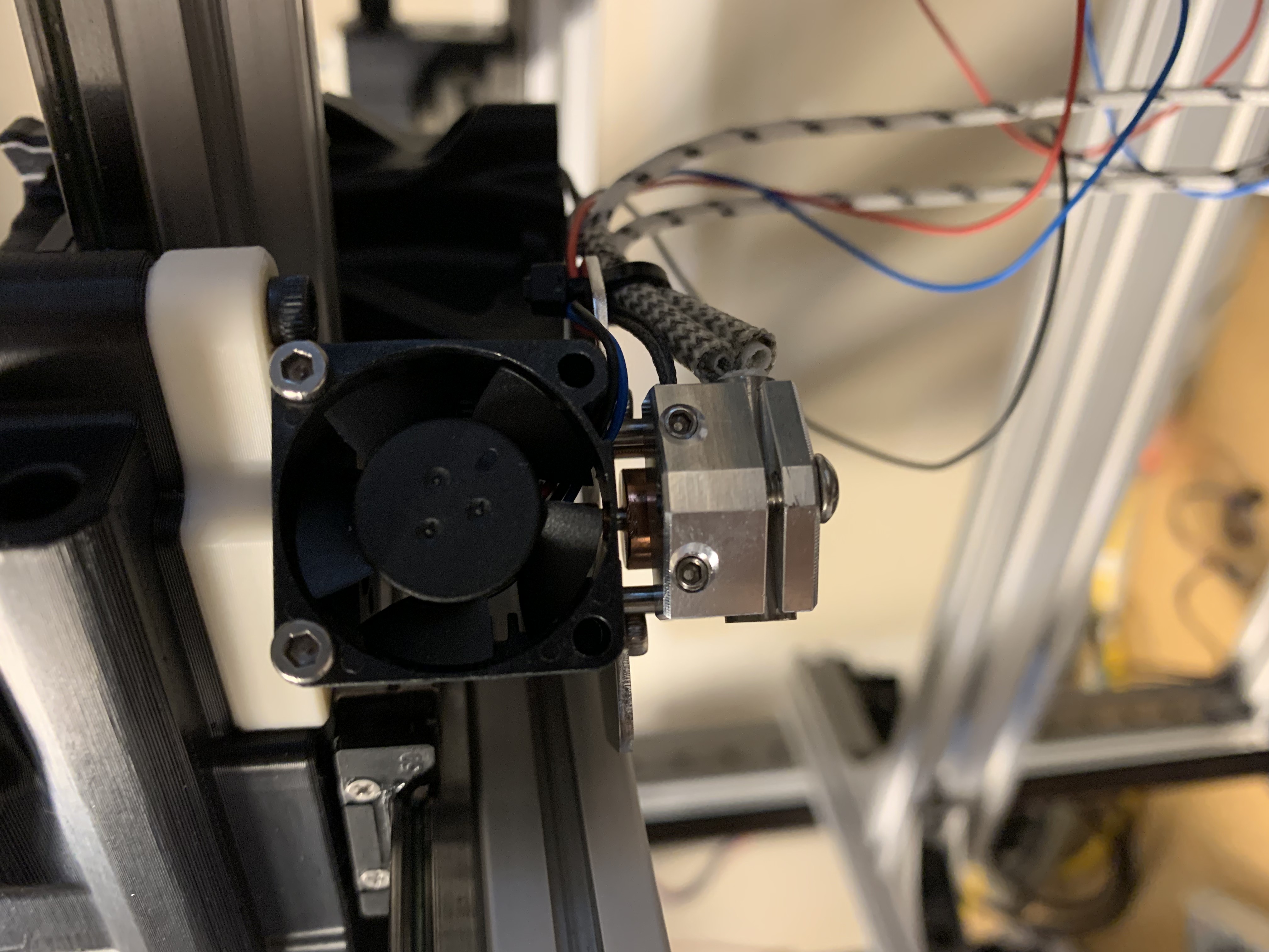
Figure 16: Tool installation, front bolt
If you’re using a mosquito net, bolt the net to the toolhead using 2x M3x8 BHCS, use loctite.

Figure 17: Tool installation, mosquito net attachment
Use 4x M3x35 SHCS to loosely attach the toolhead to the Y cross rail carriage.
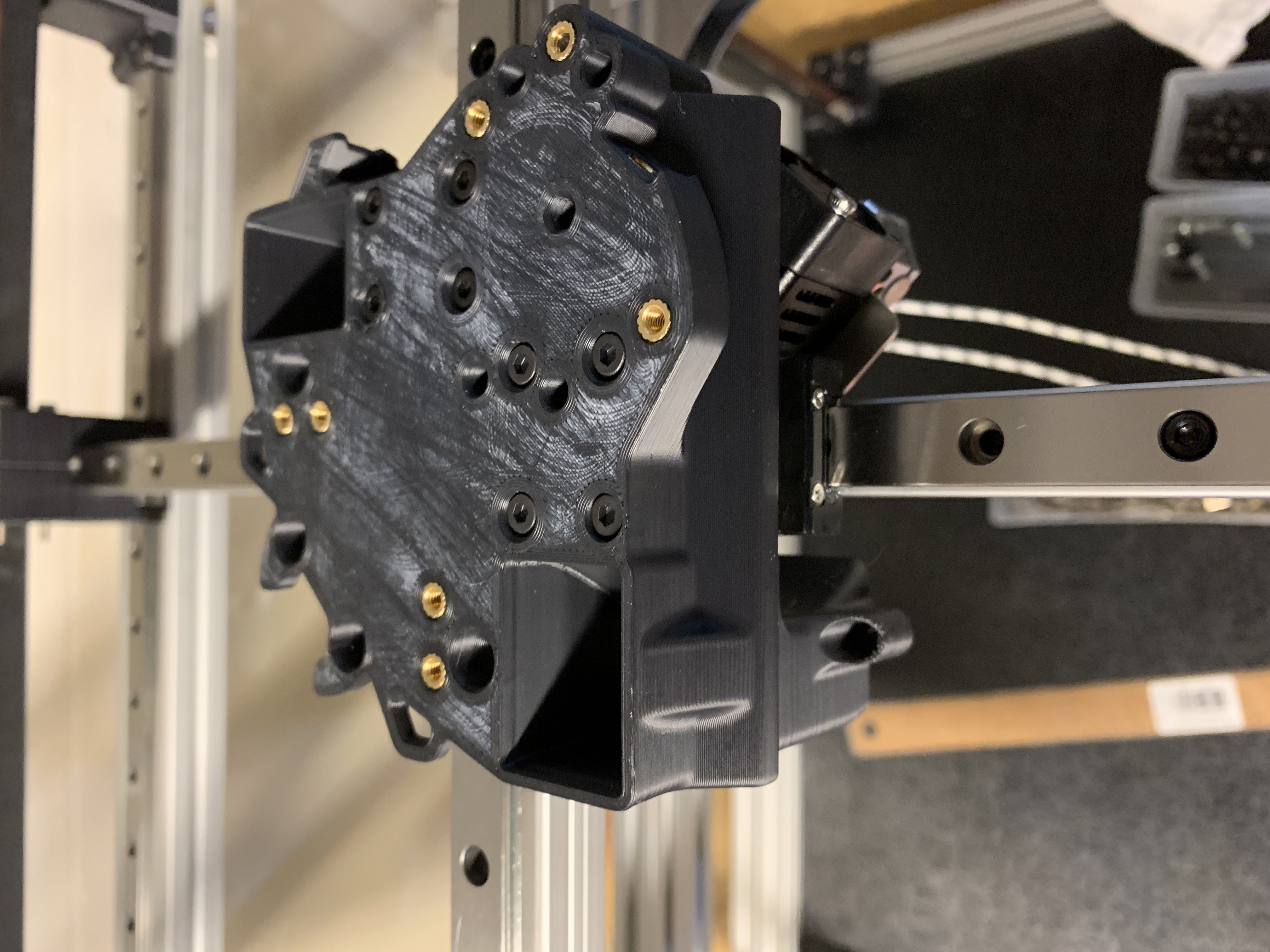
Figure 18: Toolhead installation, Y cross rail carriage bolts
The bolts attaching the toolhead to the X and Y cross rail carriages will be tightened after we’ve homed the printer for the first time, so don’t worry about them for now.
Probe mount
Heatsets
Insert 4x M4 (center of the printed part) and 2x M3 Tall (periphery of the printed part) heatset inserts into the bottom of the probe mount printed part
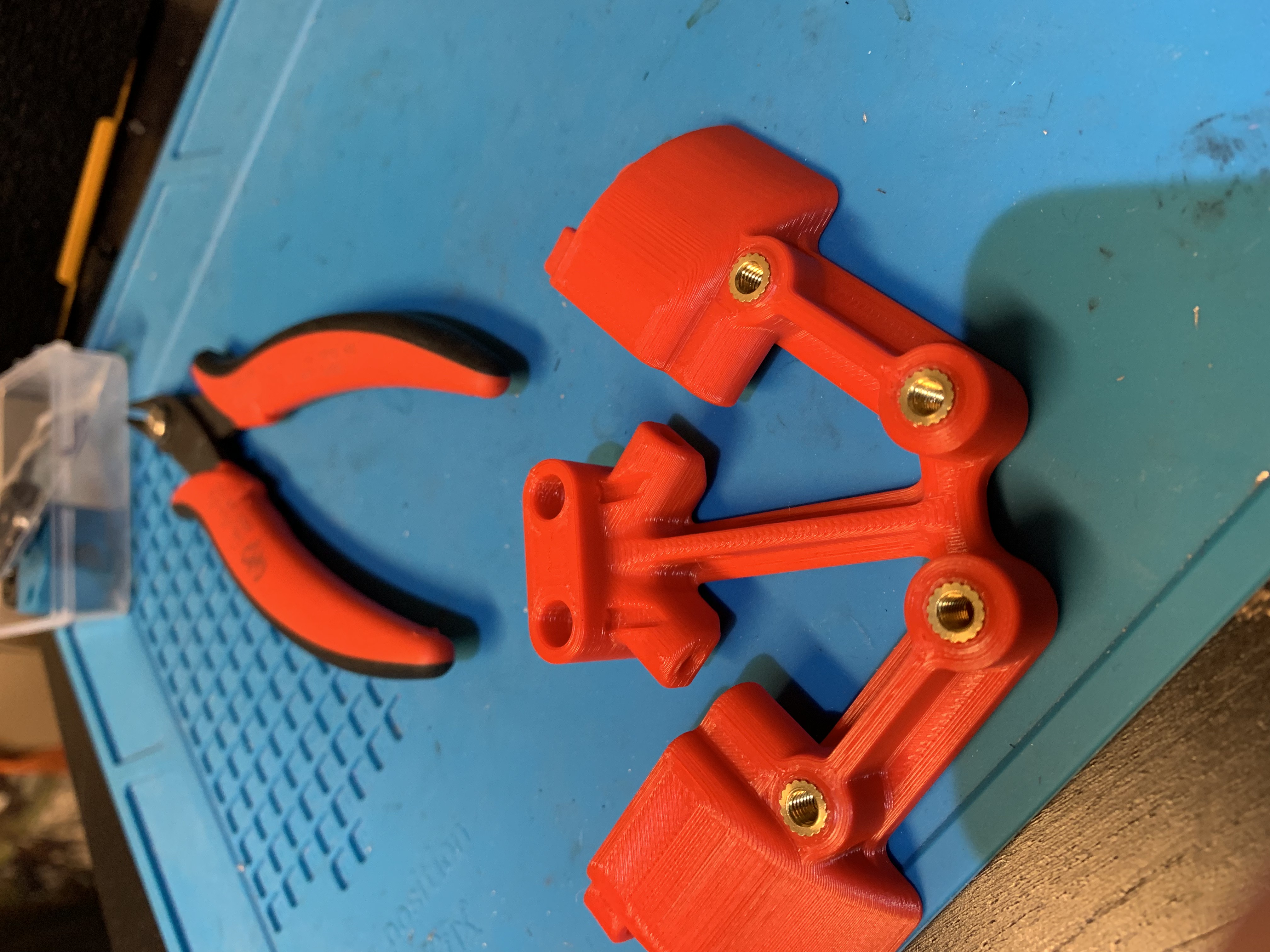
Figure 19: Heatset inserts for bottom of the probe mount
Now for the hard part: we need to insert 2x M3 Tall heatset inserts into the sides of the fan duct exits. There isn’t a lot of space to work with, so it needs some finesse.
Put the heatset insert in place and thread an M3 bolt through the printed part into the insert
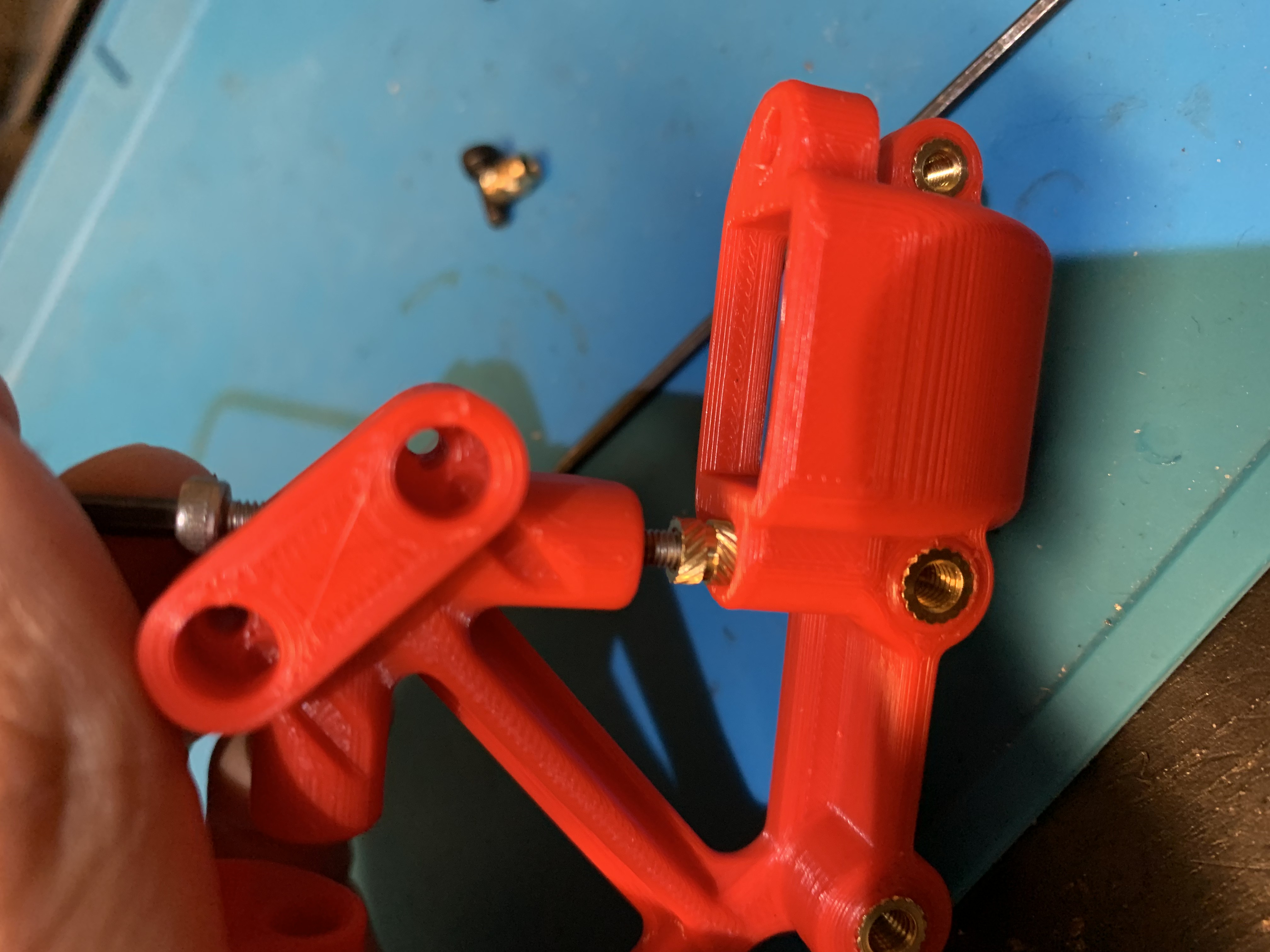
Figure 20: Heatset insert with bolt threaded in
Use a hex driver to apply pressure on the bolt
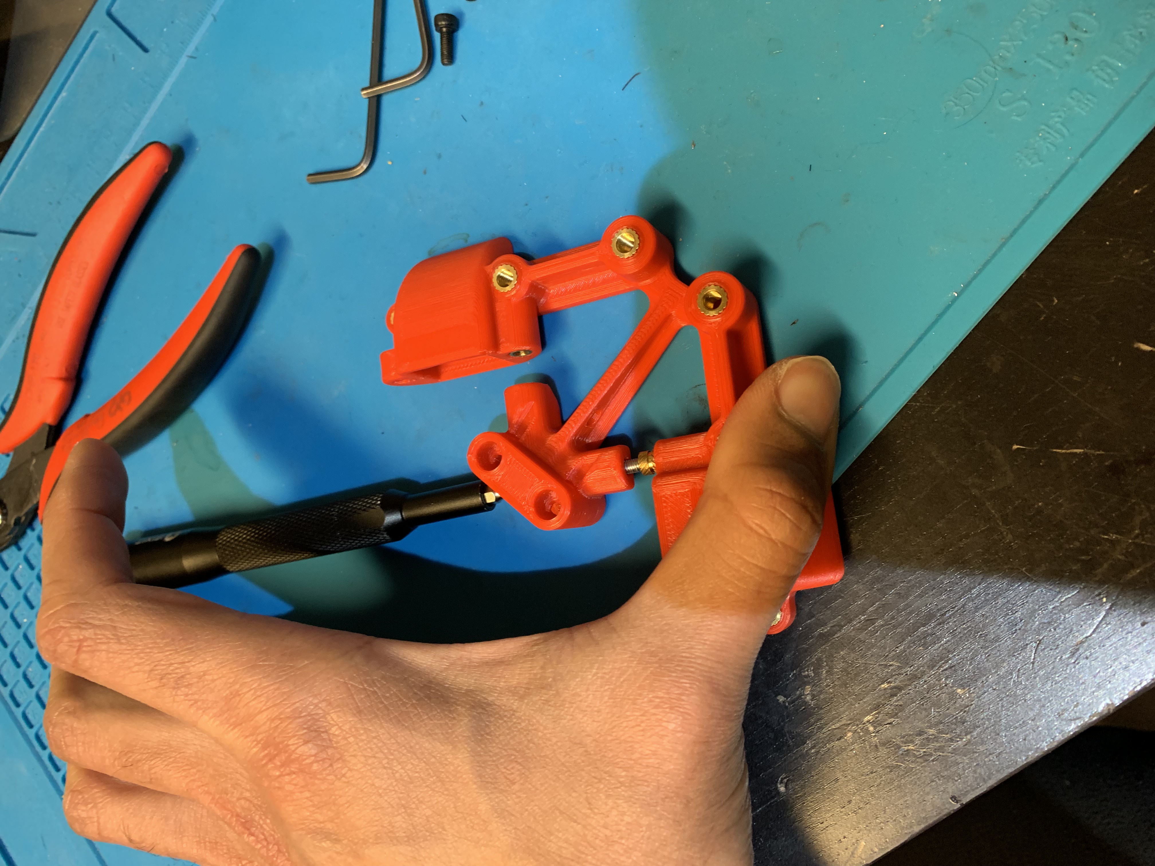
Figure 21: Hex driver applying pressure on the bolt’s head inside the printed part
Use your soldering iron to heat the heatset insert from the side. I ended up having to run my iron at 350 F for this to work
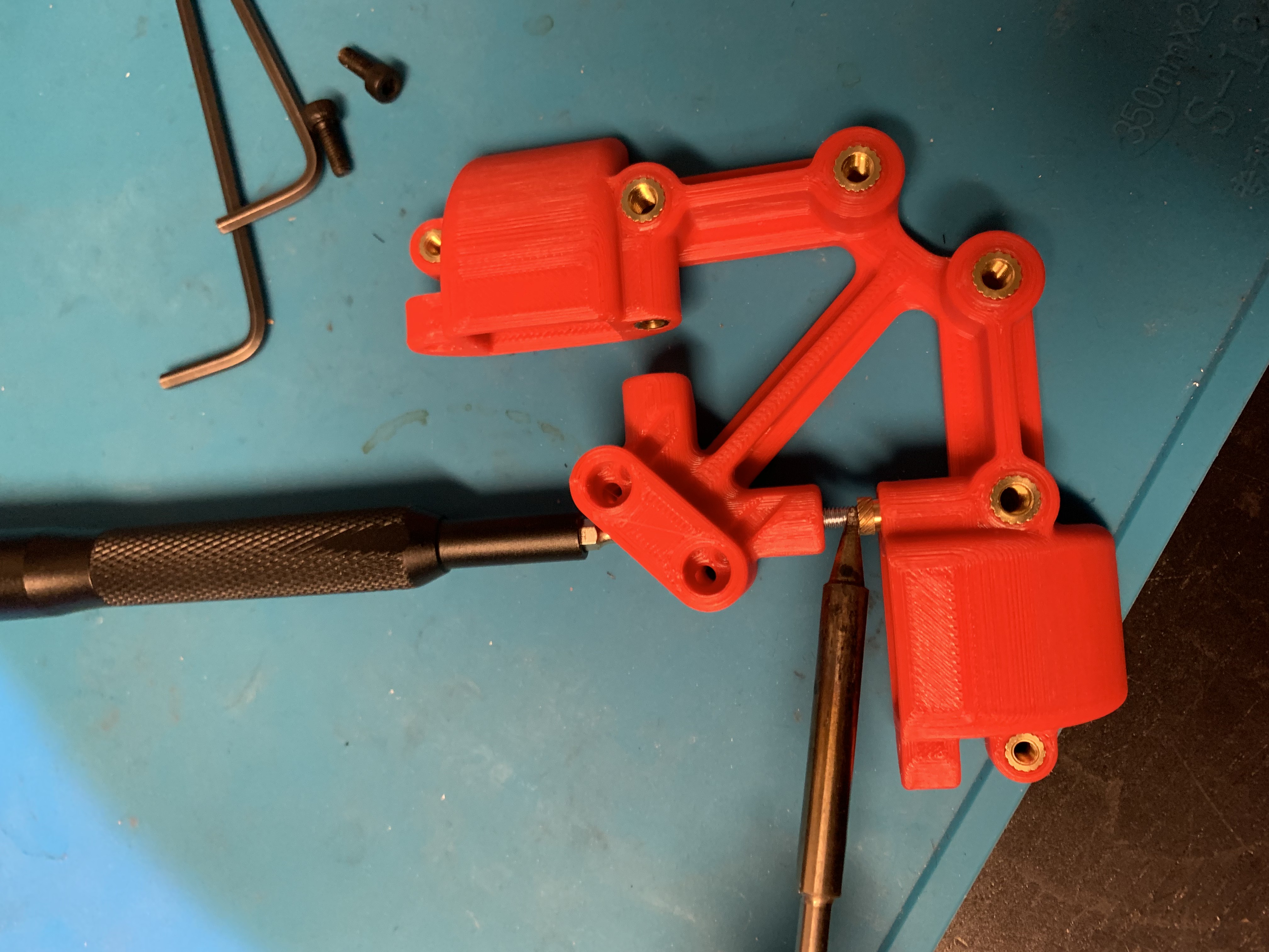
Figure 22: Soldering iron applied from the side of the heatset insert
With time and constant pressure, the heatset insert should slowly slide into place. Once it’s almost all the way in, I found it useful to remove the bolt and just use the iron to slowly push it in place while being careful to not melt the surrounding plastic.
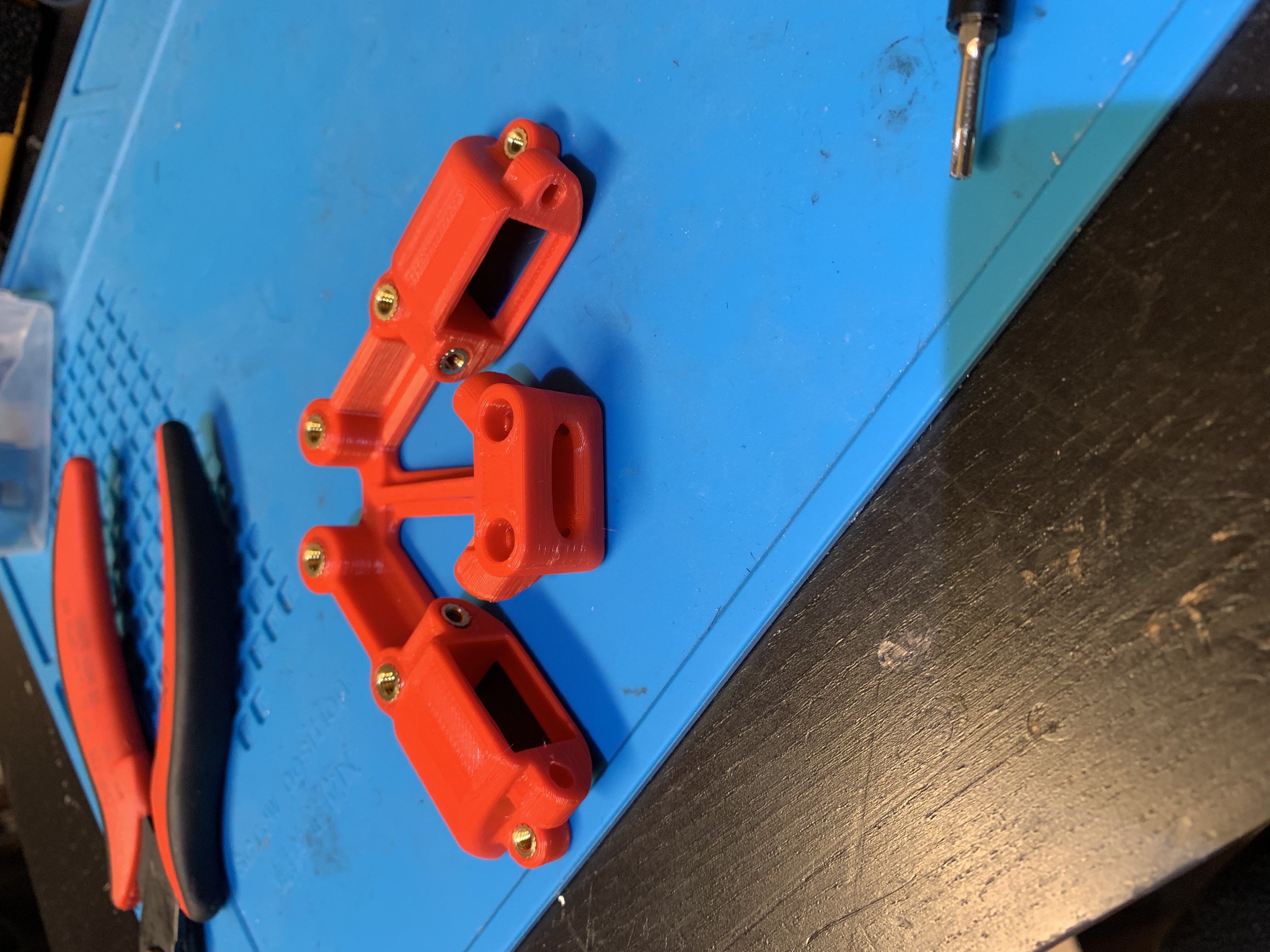
Figure 23: Painful heatset inserts, installed
Wires and magnets
Take two wires and slide them in through the channels at the bottom of the printed part. Pull the ends up and out through the printed part, then strip off about 1 cm of insulation from the ends of the wires. Fan out the strands of the wires, and pull them back out of the printed part till the insulation is flush with the edges of the printed part.
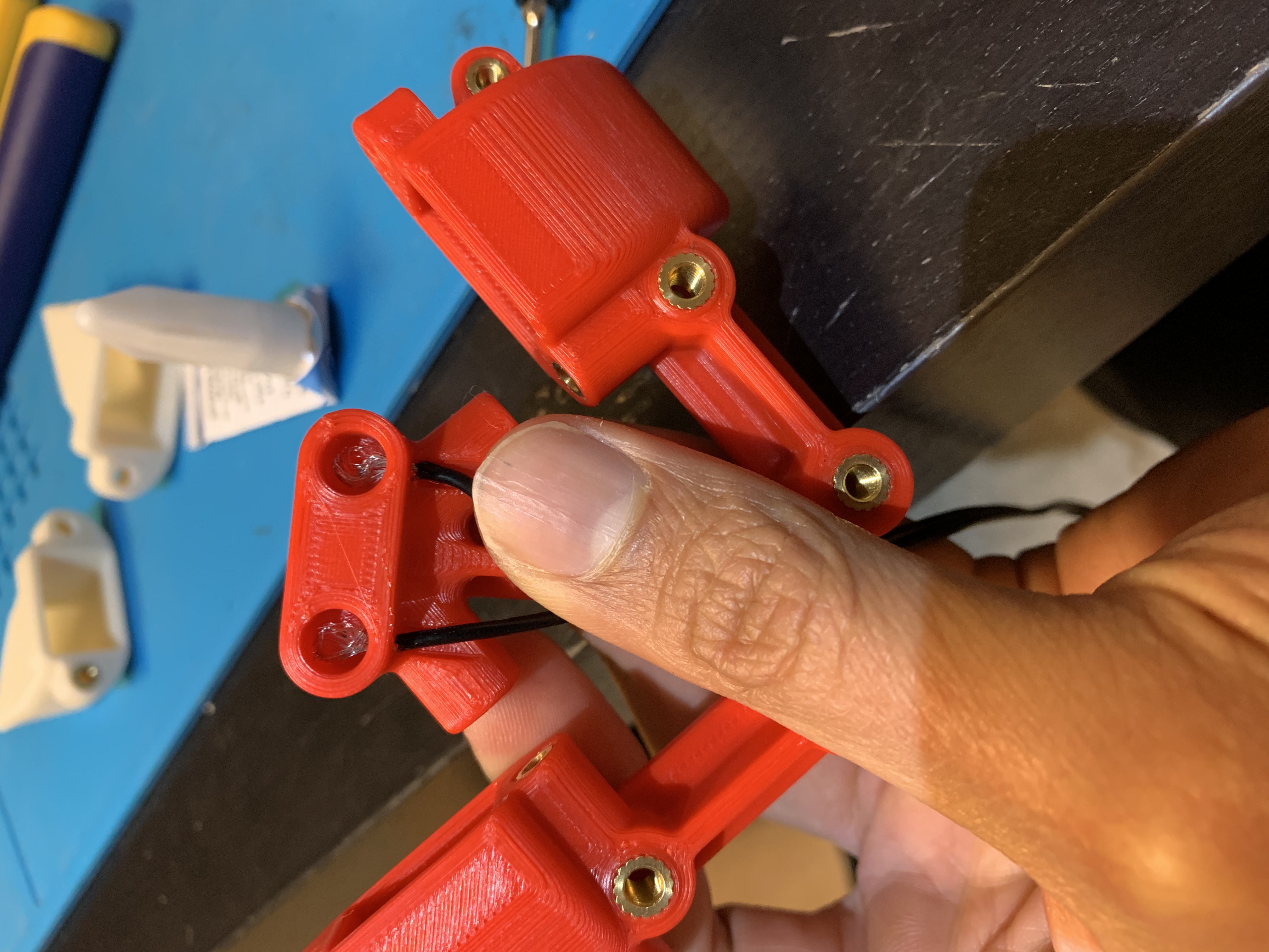
Figure 24: Wires inserted into the probe mount
Take two 6x3 magnets and push them into the probe mount. Use a non-abrasive flat surface like a table top to push them in until they squeeze the wires and are flat with respect to each other.
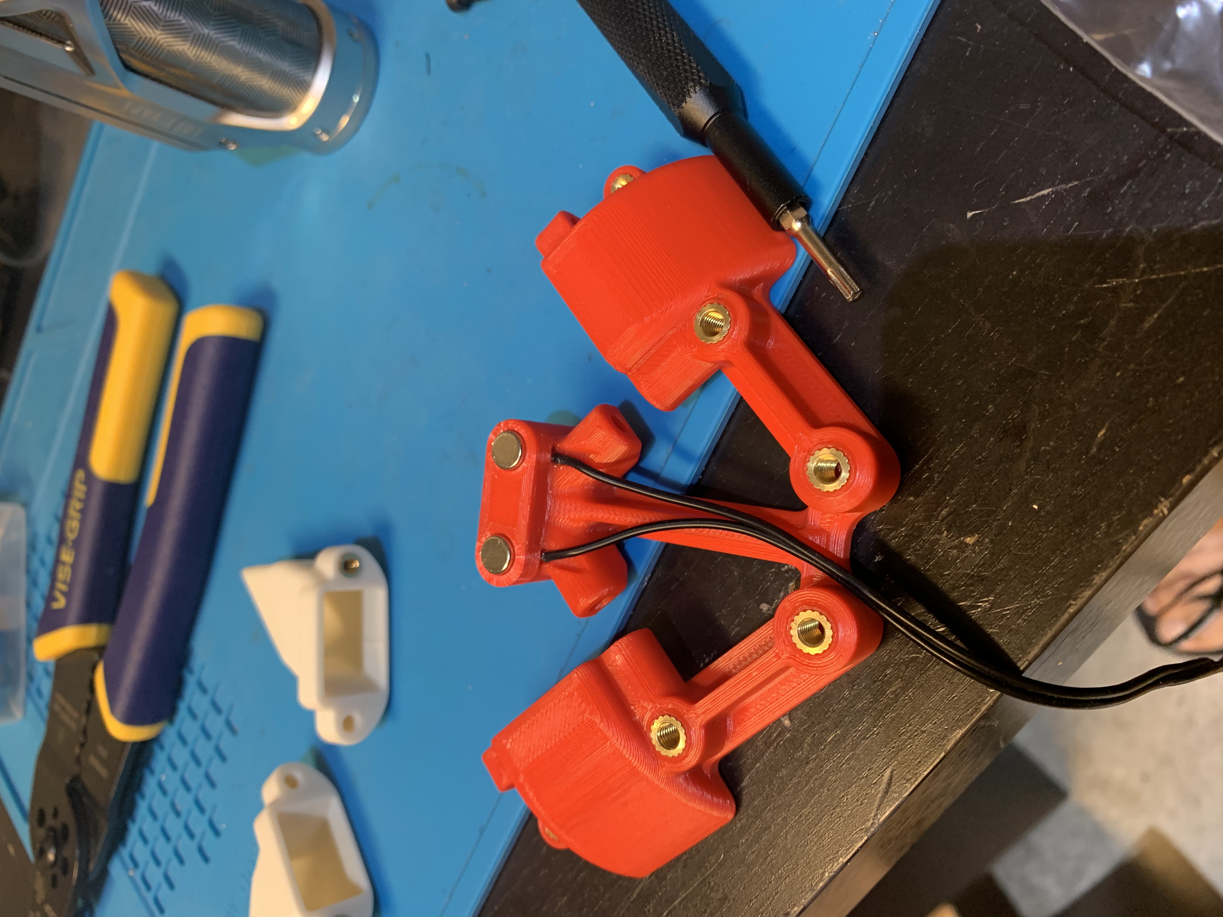
Figure 25: Magnets inserted into the probe mount
Fan ducts
Heatsets
Insert 1x M3 tall heatset insert into each fan duct
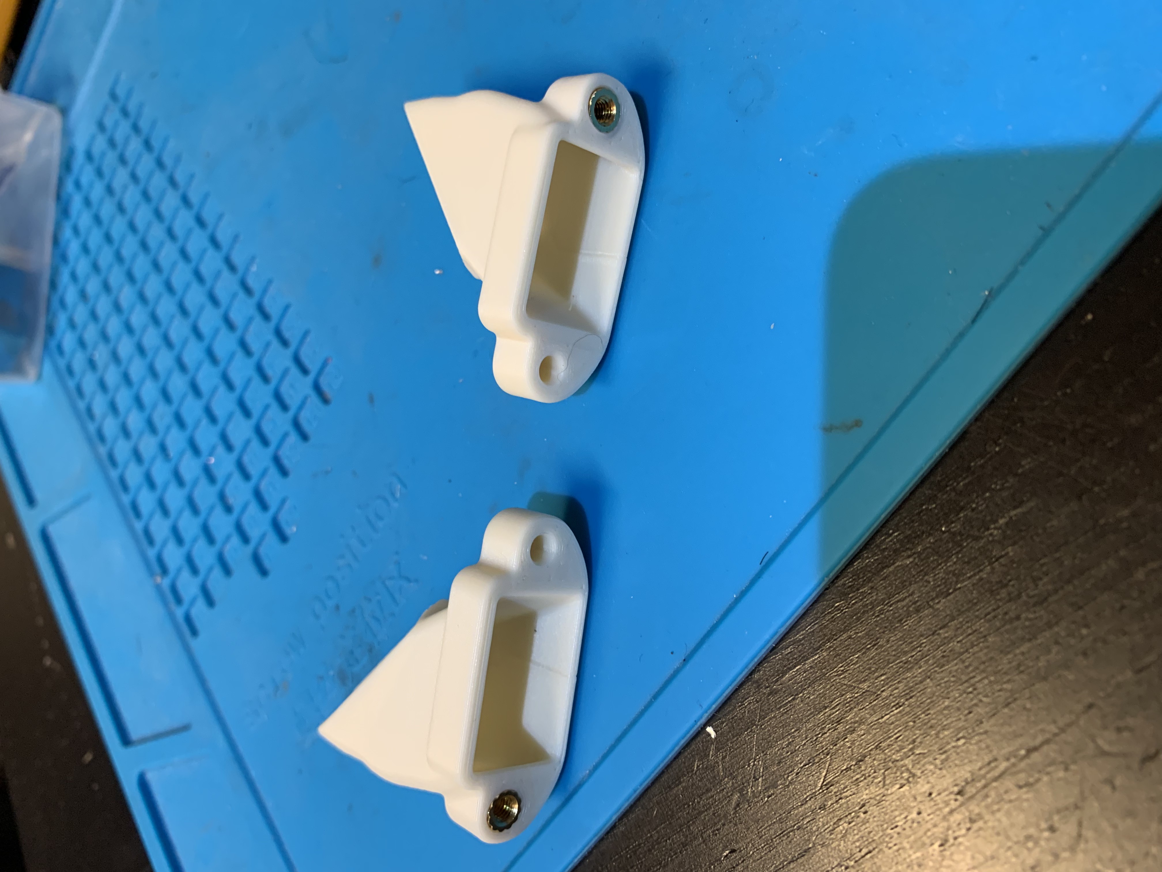
Figure 26: Heatset inserts for fan ducts
Installation
Slide each fan duct into the slot in the probe mount. Pay attention to the orientation of the duct. Use an M3x25 SHCS inside the probe mount to hold one end of the duct in place
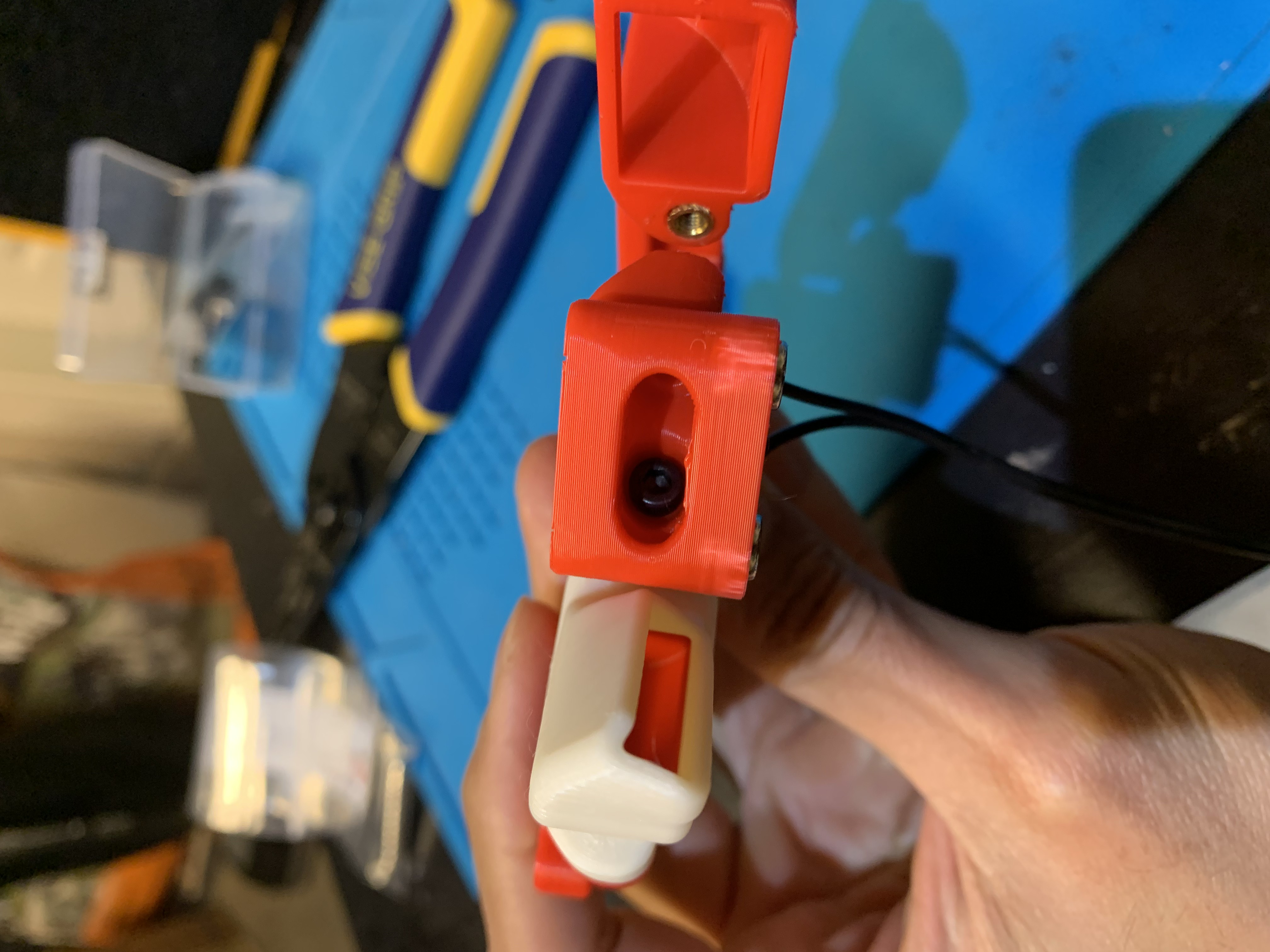
Figure 27: Fan duct attachment, inside bolt
Use an M3x10 SHCS on the outside to hold the other end of the duct in place
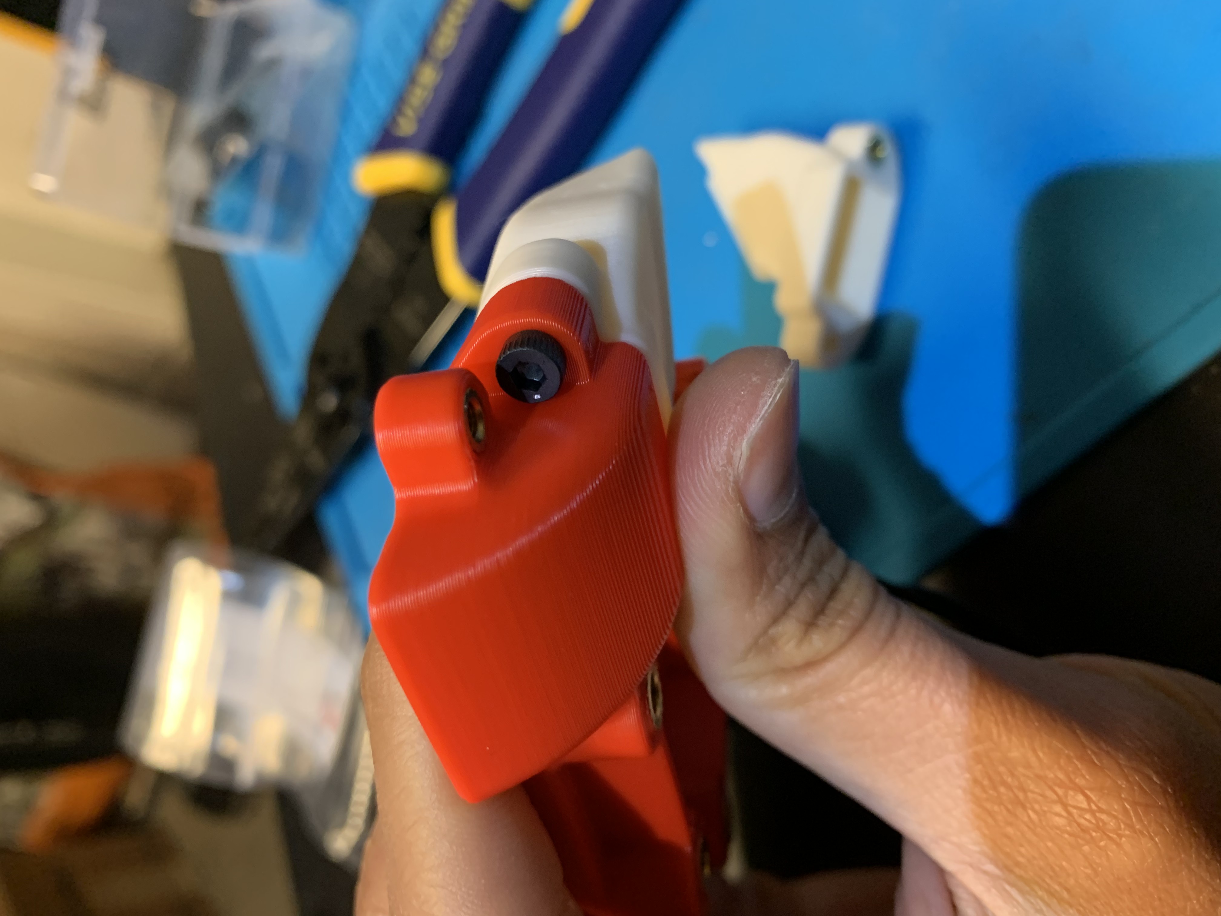
Figure 28: Fan duct attachment, outside bolt
Repeat for the other duct
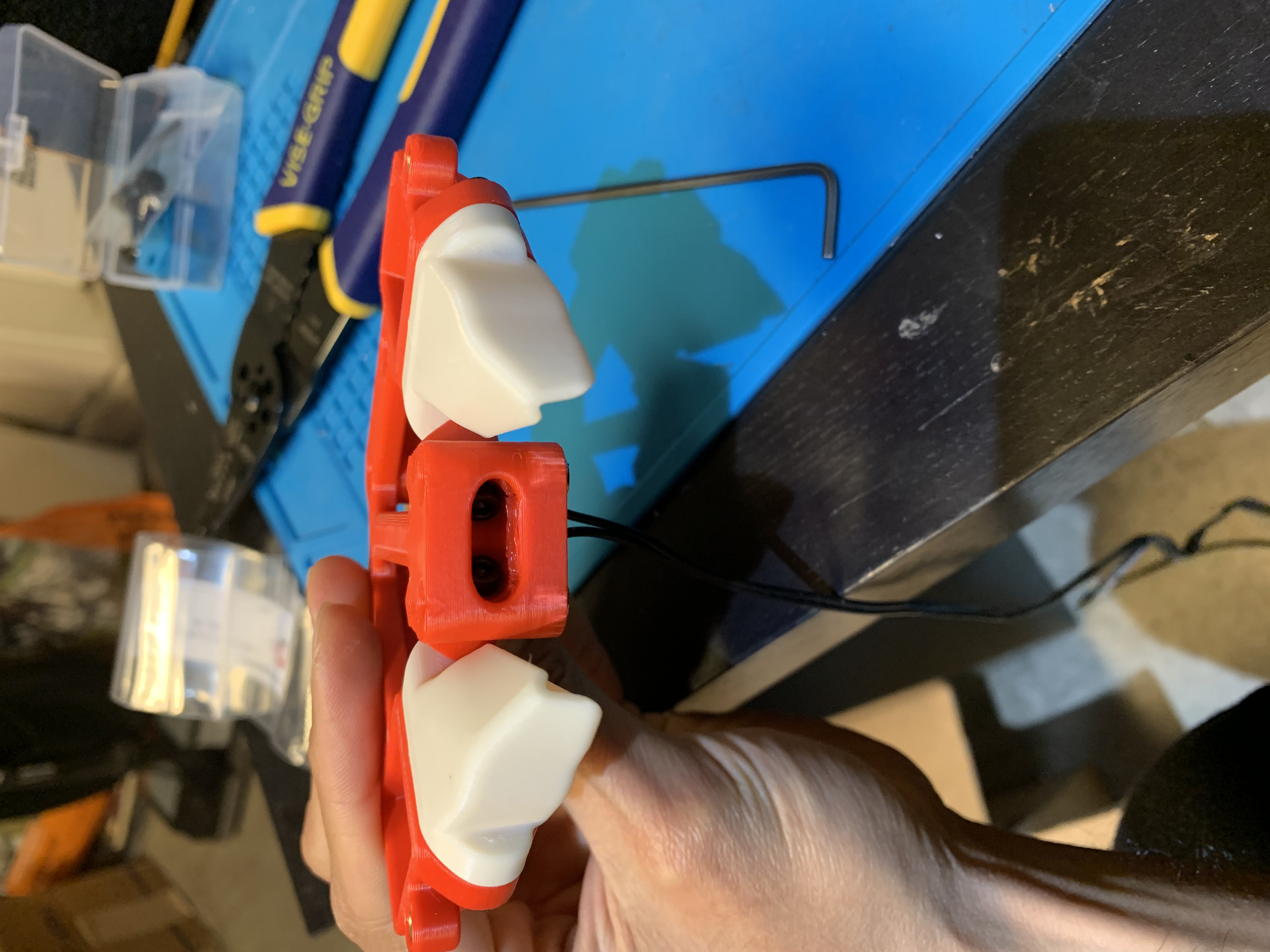
Figure 29: Fan ducts and probe mount, front view
Use a ziptie to hold the wires in place
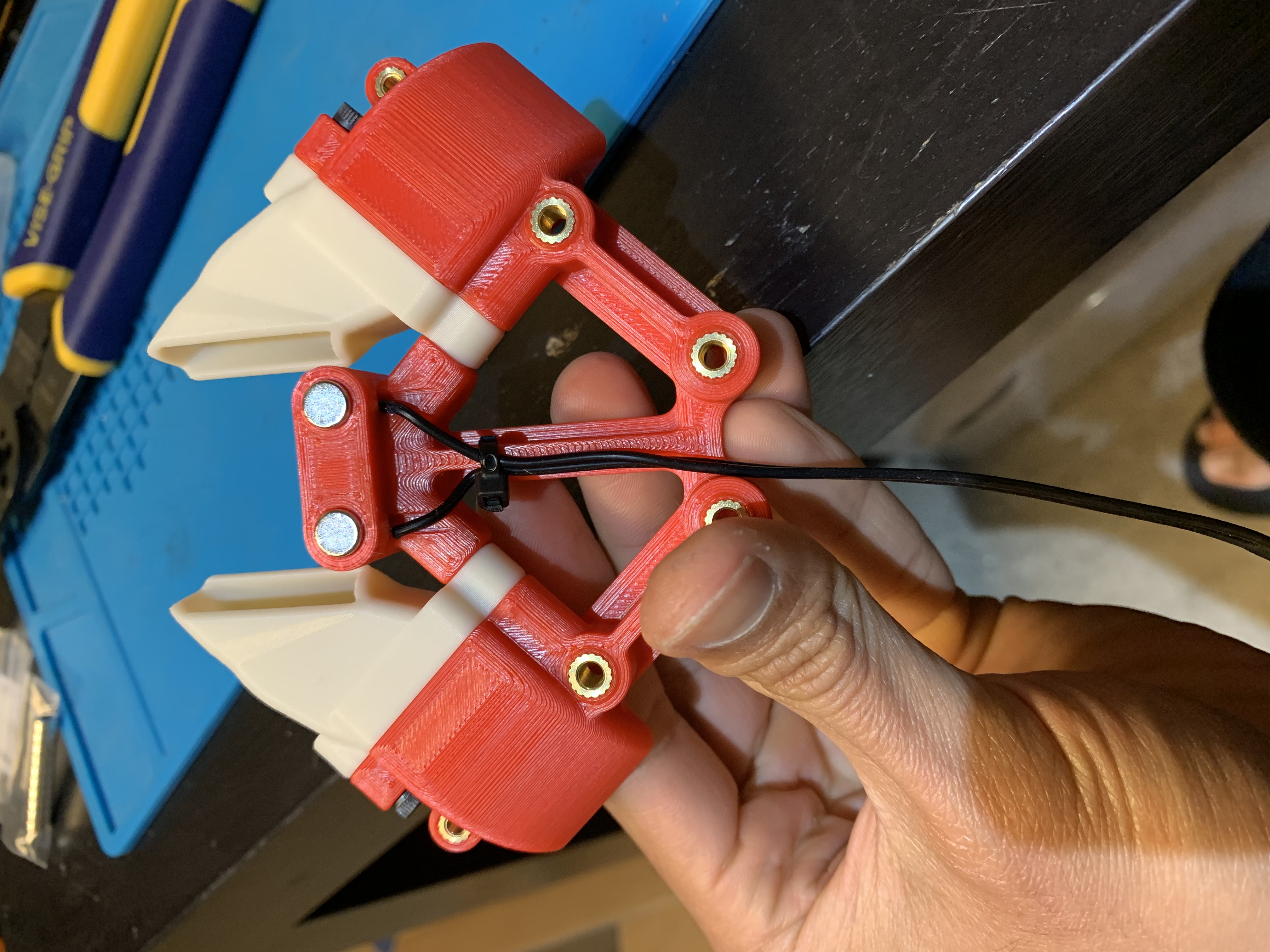
Figure 30: Fan ducts and probe mount, bottom view with zip tie
Toolhead bottom installation
With the toolhead bottom comprised of the probe mount and fan ducts in hand, let’s attach it to the installed toolhead. Install 4x M4x70 SHCS as shown
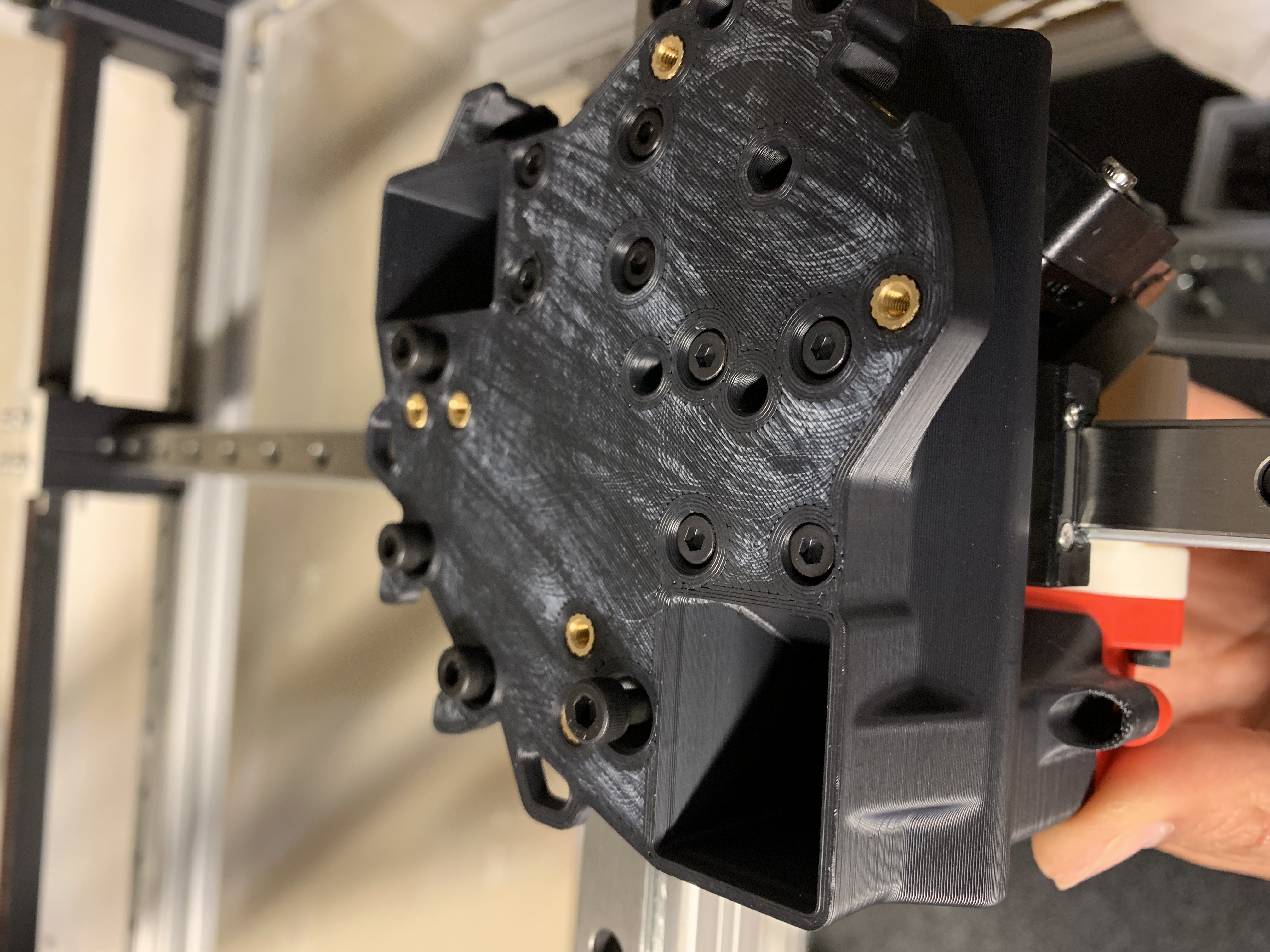
Figure 31: M4x70 bolts to attach the toolhead halves
Hold the toolhead bottom in place and bolt it to the top by tightening the M4x70 bolts. Use 2x M3x10 SHCS to finish attaching the bottom to the top.
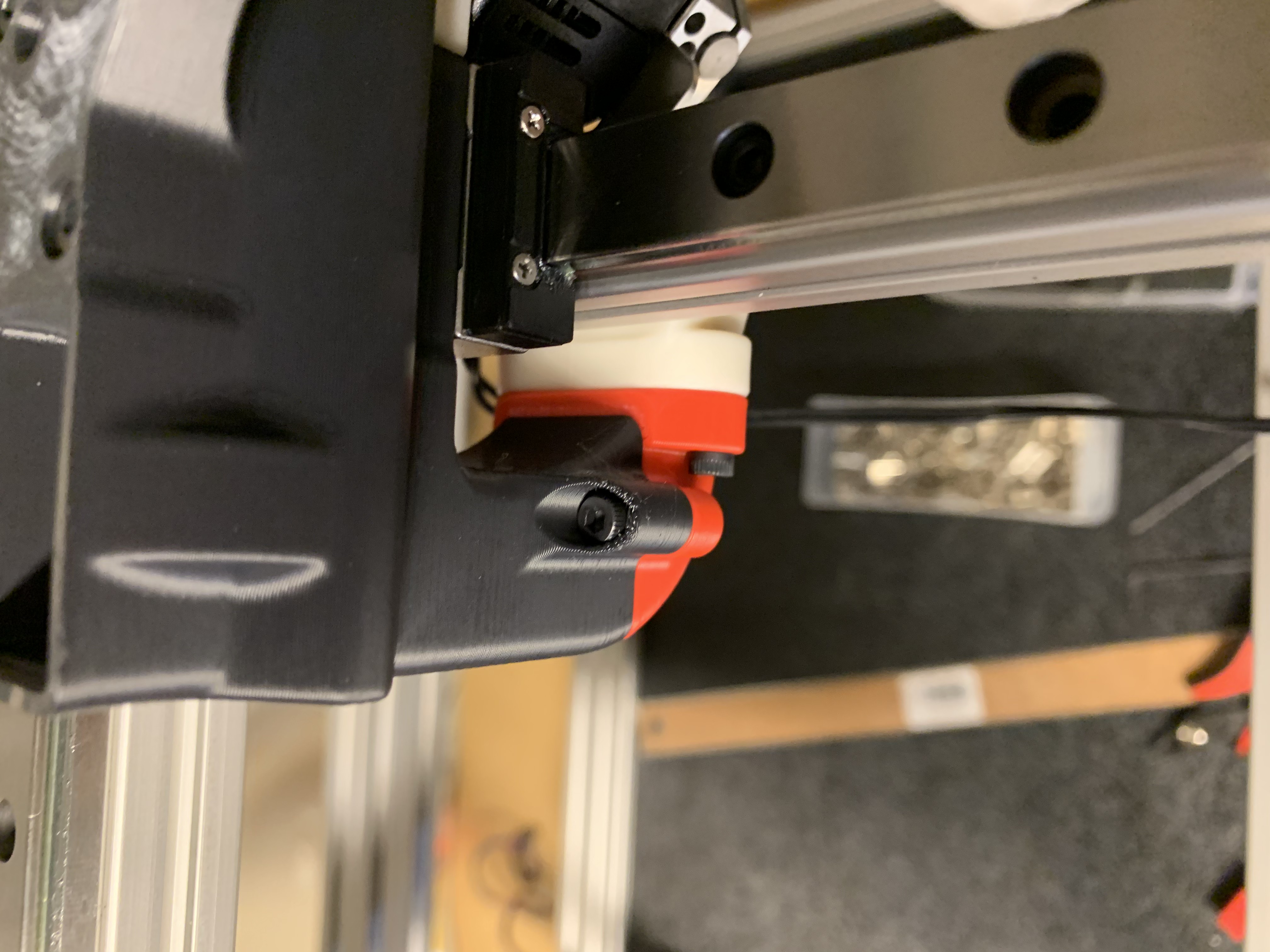
Figure 32: M3x10 bolts to attach the toolhead halves
Once that’s done and both halves are well aligned, remove the six bolts one at a time, apply loctite and screw them back in.
Side note: my toolhead bottom is red in the above pictures and will be black in the below ones. Don’t be confused: I was trying a modified probe holder (red) that didn’t work out, so I switched to using the stock one (black).
Fans
Fan mounts heatsets
Insert 3x M3 Tall heatset inserts into each fan mount
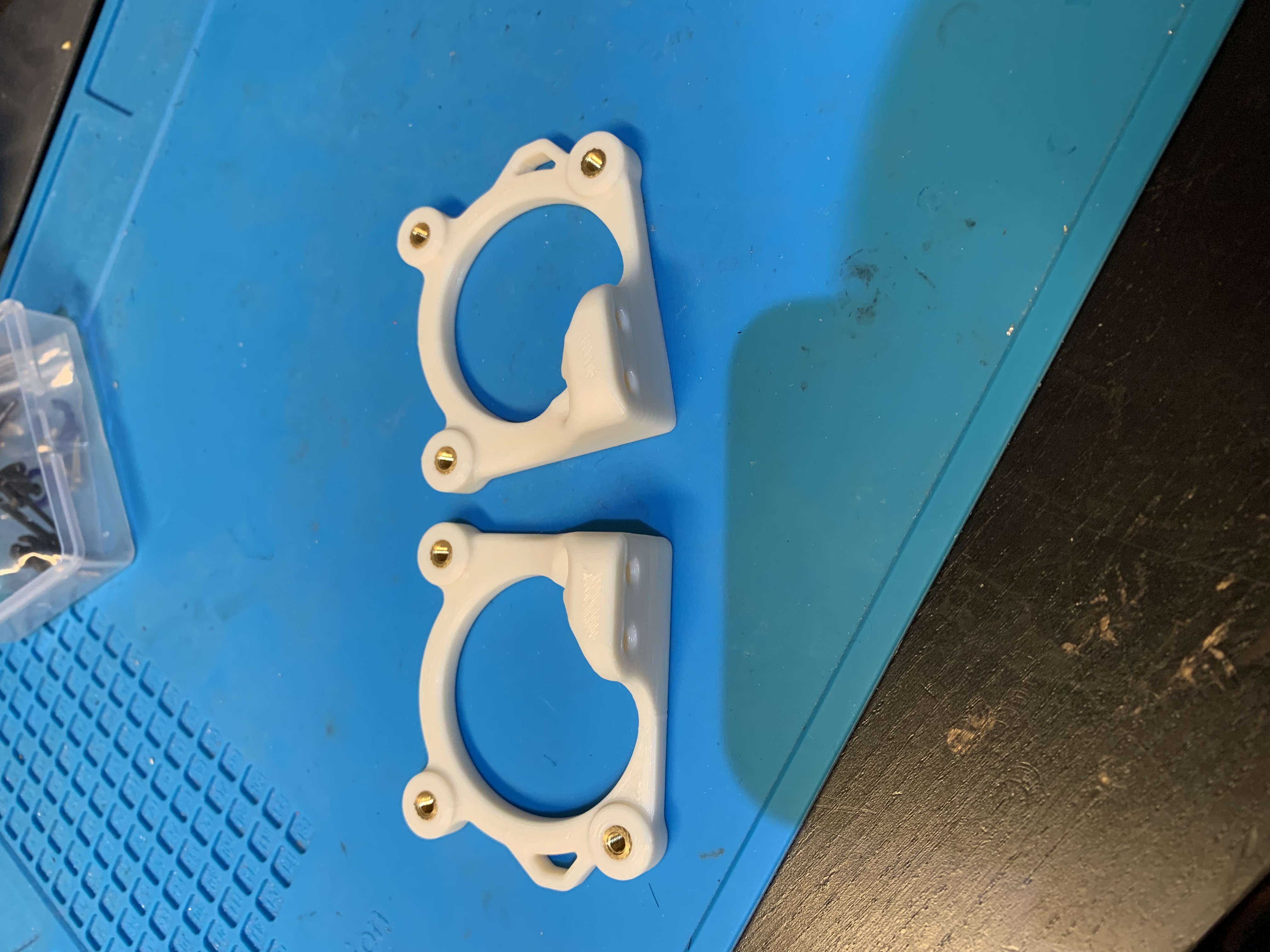
Figure 33: Heatset inserts in fan mounts
Place the left fan mount on the toolhead and loosely bolt it using 2x M3x10 SHCS
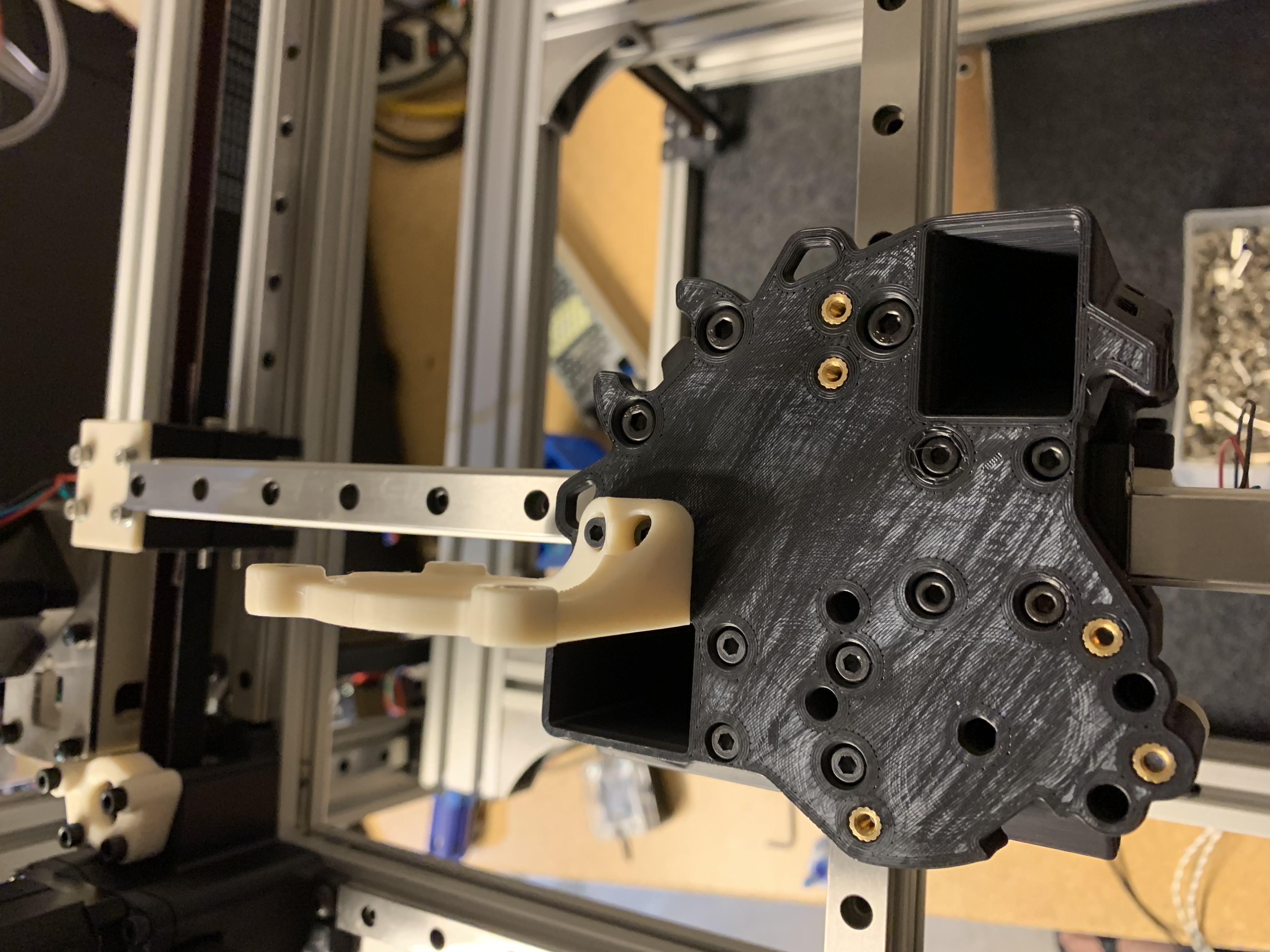
Figure 34: Left fan holder installed
Place the fan next to it and wiggle it around till it feels secure inside the duct opening and looks perpendicular to the top surface of the toolhead.
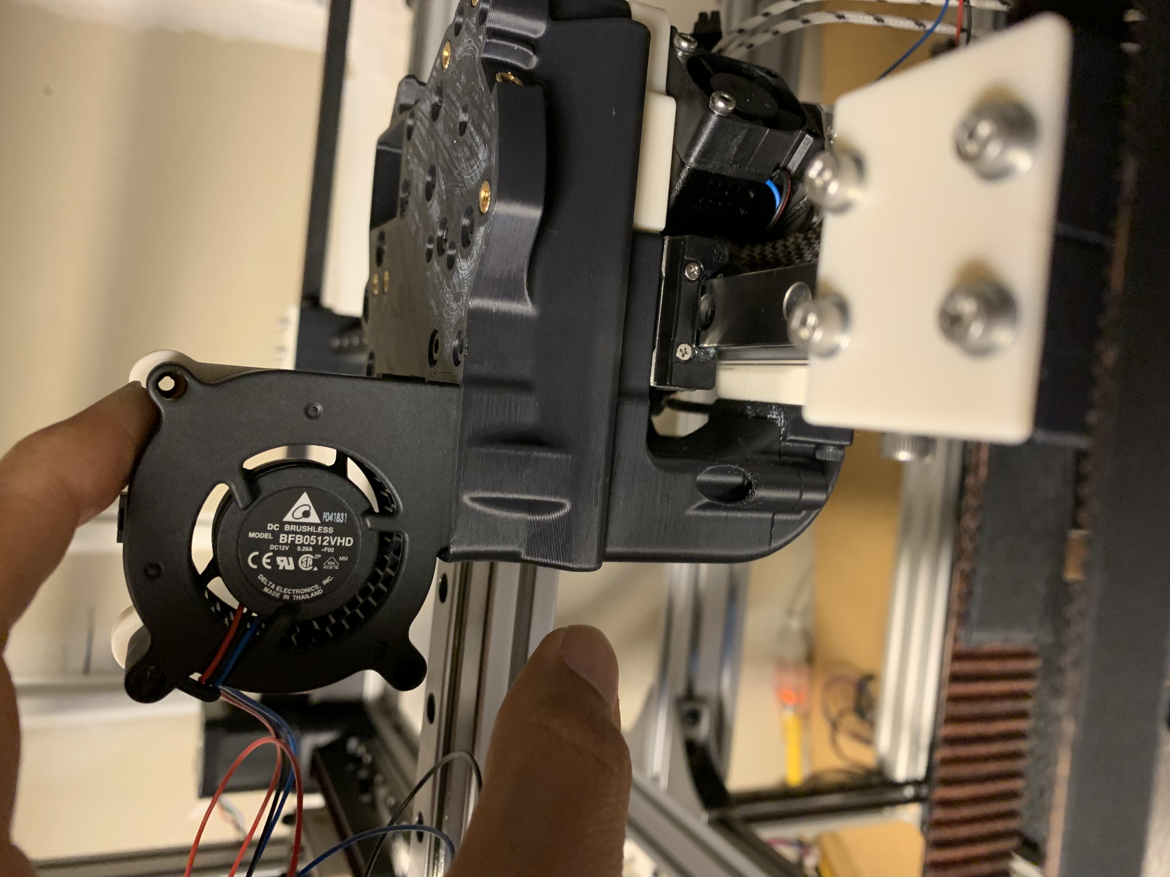
Figure 35: Left fan aligned
Attach the fan to the holder using 3x M3x25 SHCS, use loctite. Same for the 2x M3x10 SHCS you left loose earlier. My picture below only has two bolts because I was trying out something that didn’t pan out.
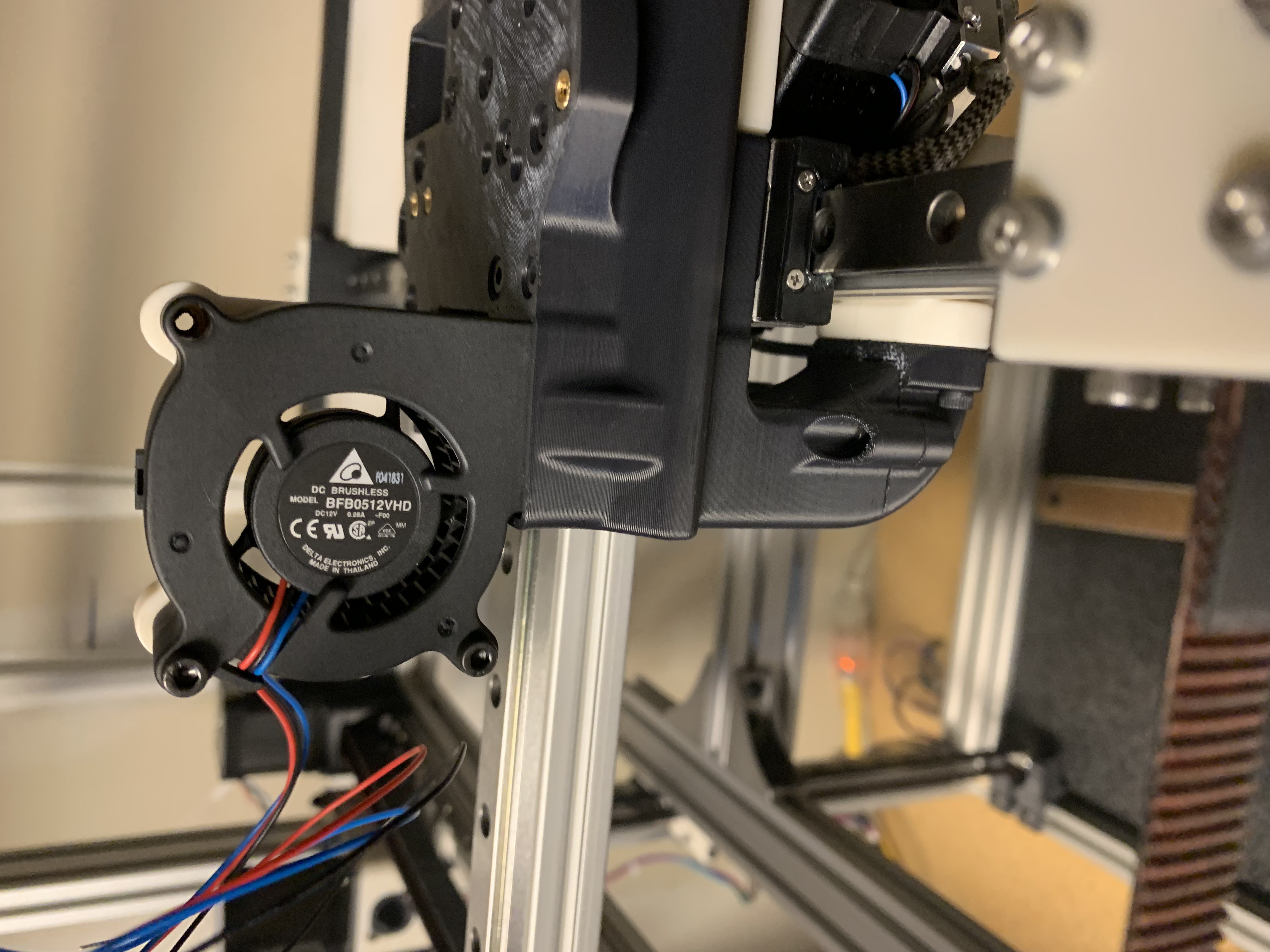
Figure 36: Left fan installed
Repeat the process for the right fan.
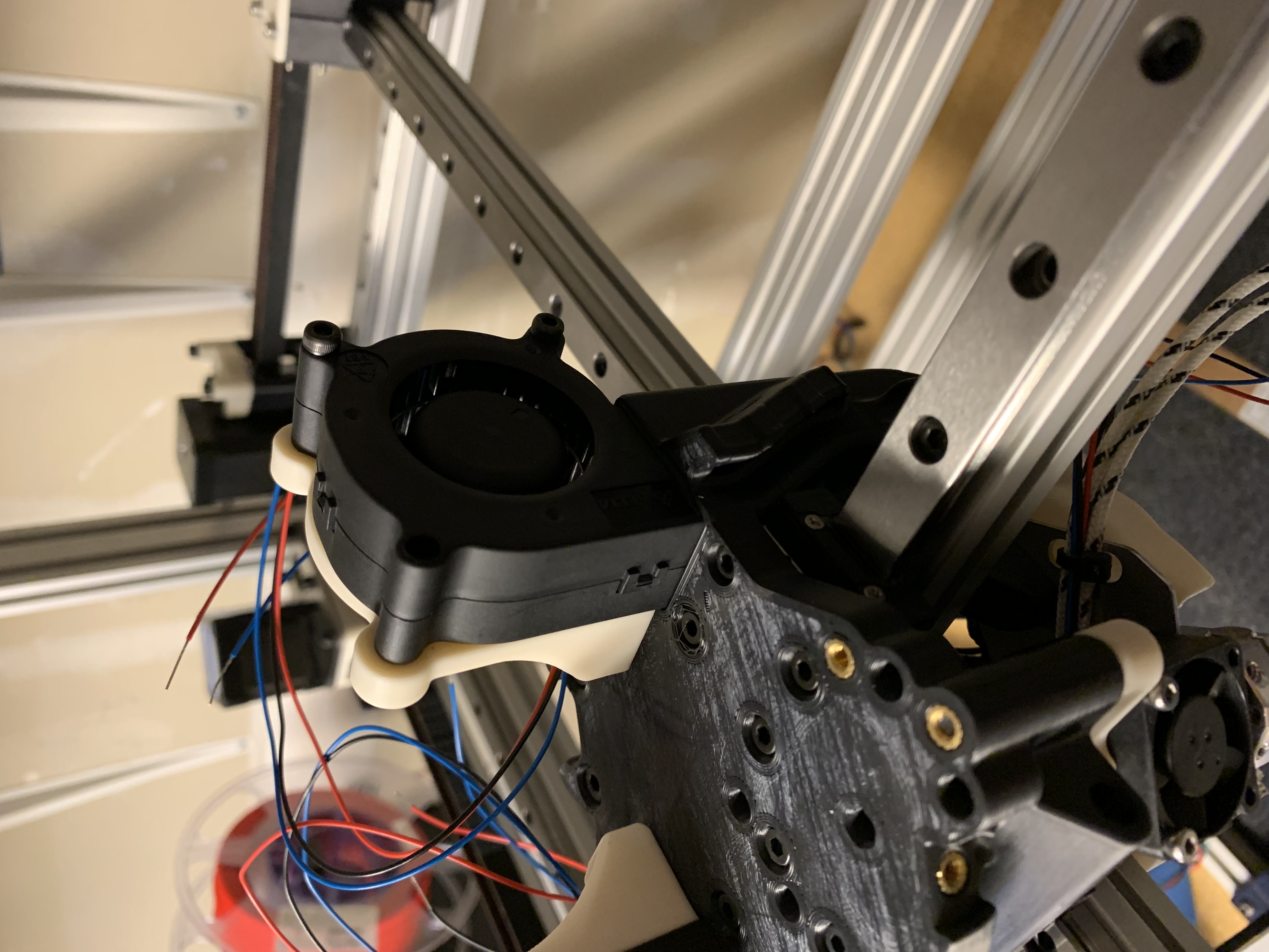
Figure 37: Right fan installed
Extruder
As described earlier, I opted to use the Sherpa Mini extruder.
Heatsets
Insert 3x M3 heatset inserts into the main housing:
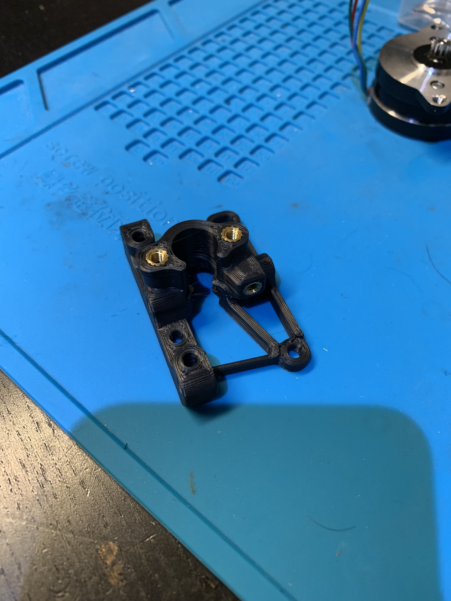
Figure 38: Heatset inserts for the main housing
Insert 2x M3 heatset inserts into the rear housing:
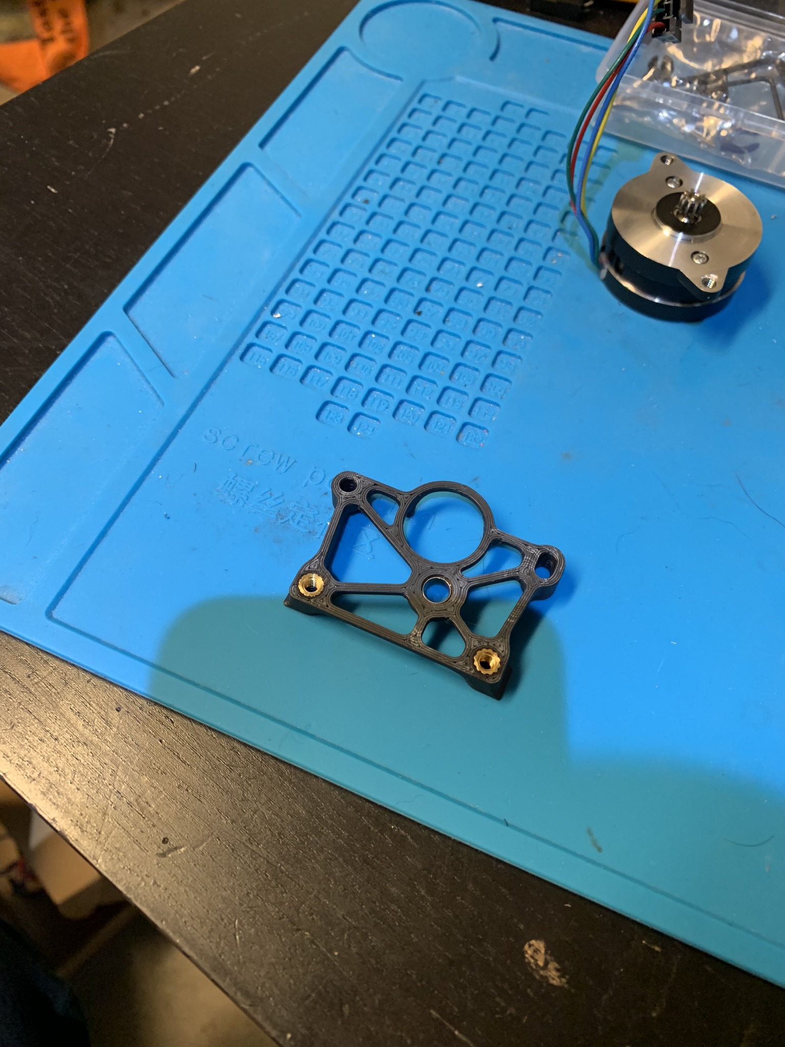
Figure 39: Heatset inserts for the rear housing
Assembly
Flip the rear housing over and insert a bearing:
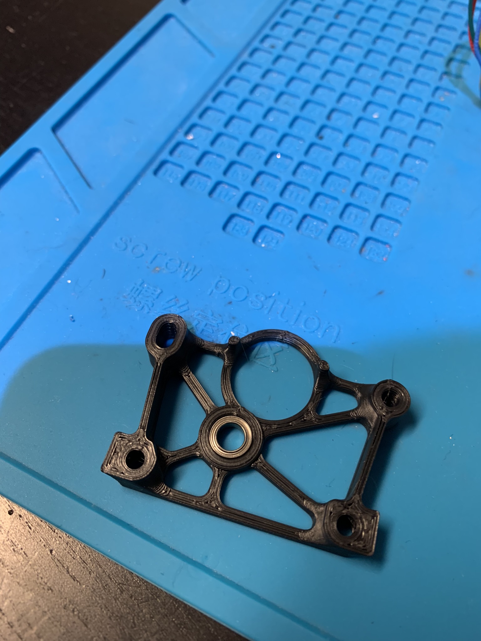
Figure 40: Bearing inserted into the rear housing
Insert the drive shaft into the bearing.
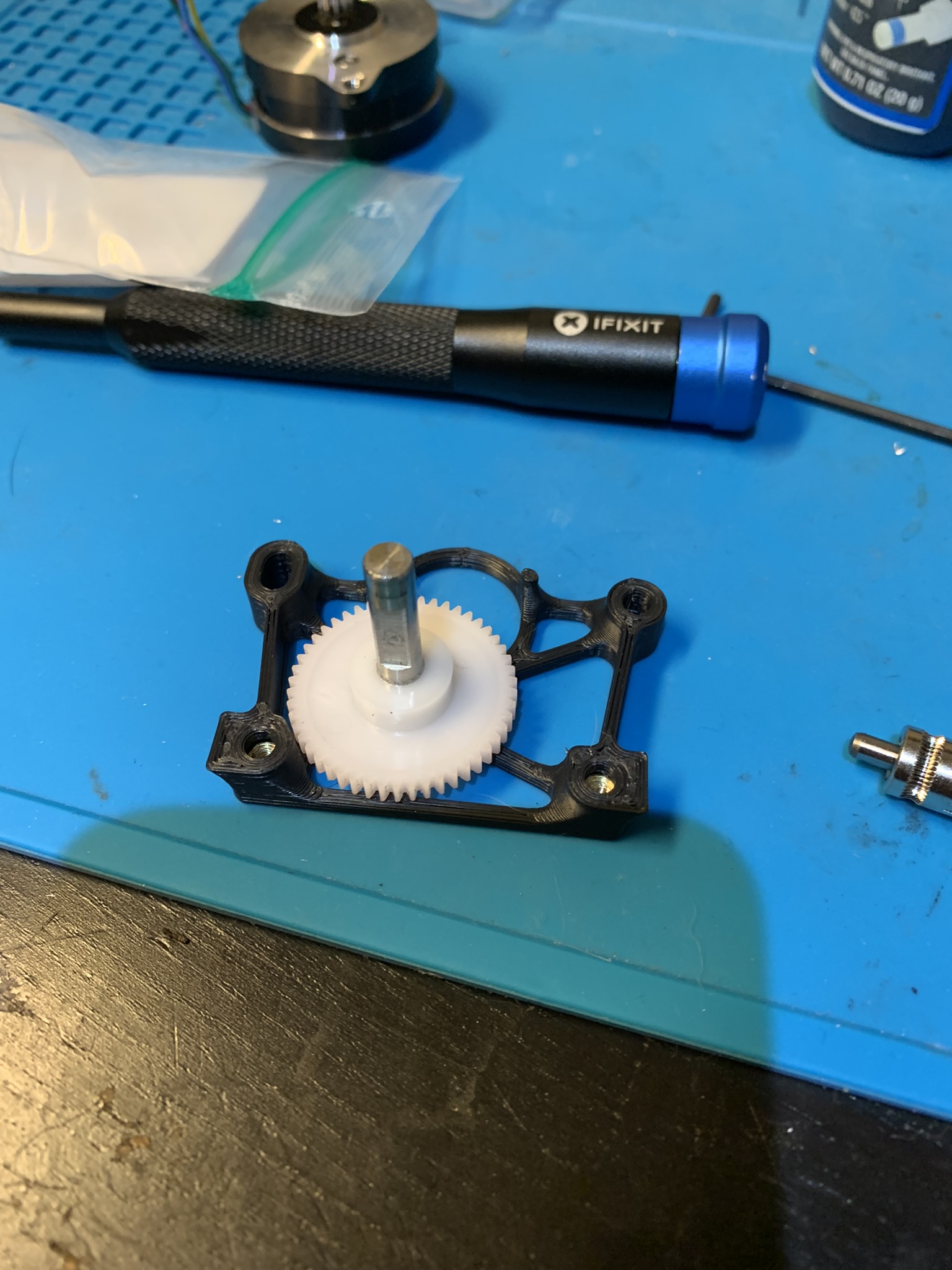
Figure 41: Drive shaft in the rear housing
Flip the rear housing and take a look at the back of the shaft. It should not protrude past the rear housing while pressing the shaft into the housing.
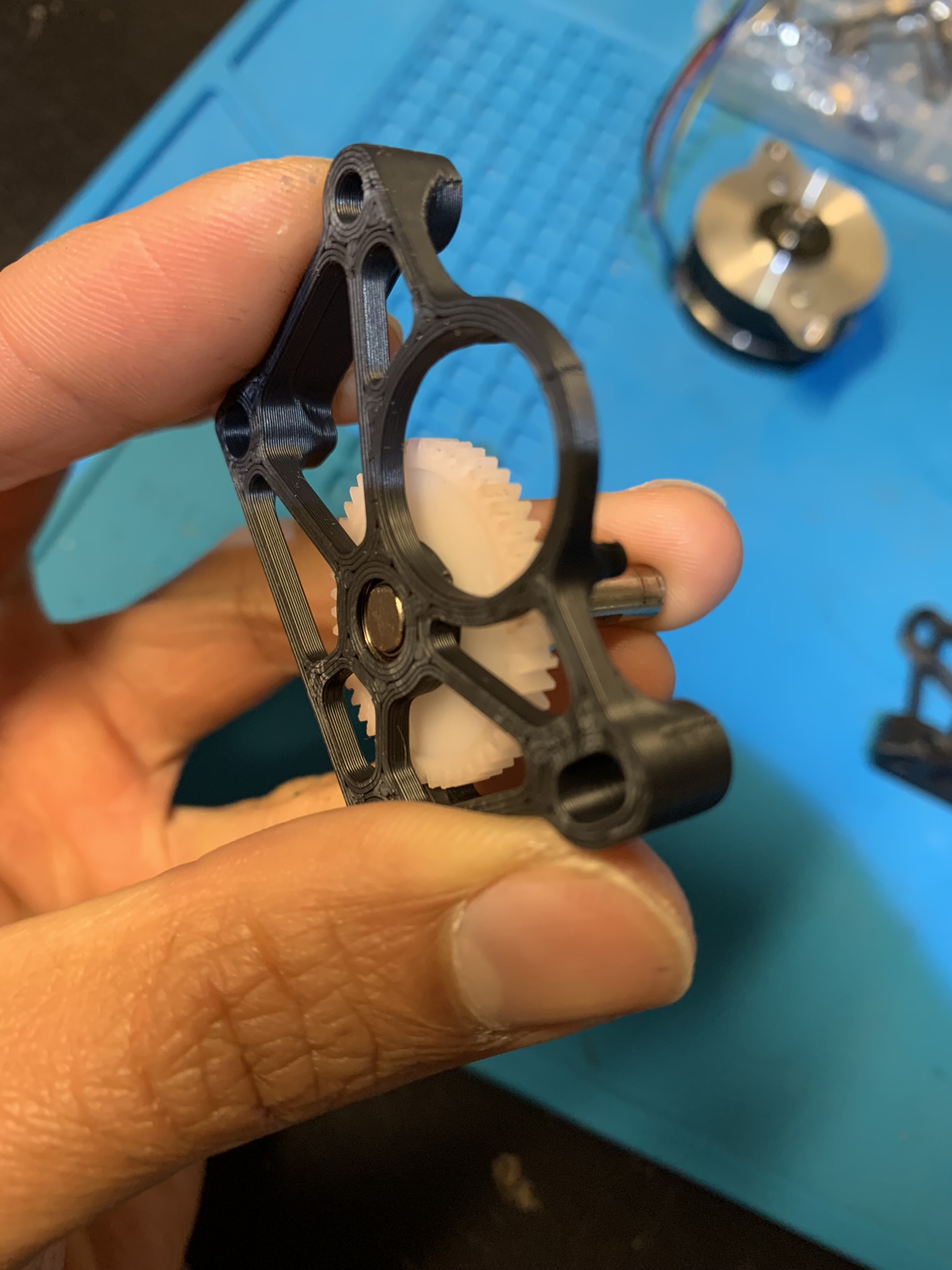
Figure 42: Drive shaft in the rear housing, rear view
If it does, print and use the shaft grinding tool to shorten the shaft, otherwise it will bore into your motor and cause you issues.
Place the main housing onto the rear housing. Attach them together using 2x M3x16 BHCS.
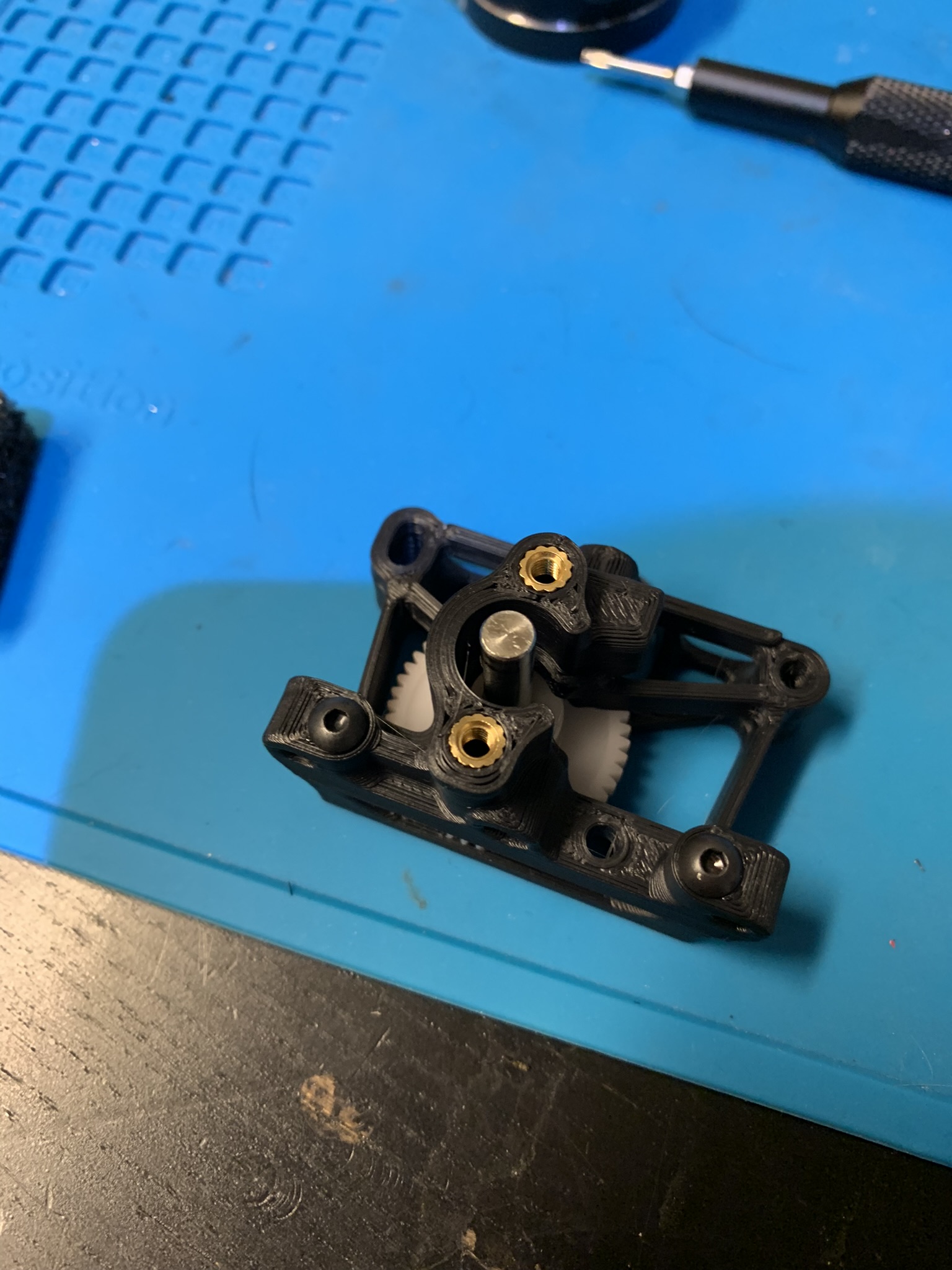
Figure 43: Main housing placed on rear housing
Insert the drive gear onto the main drive shaft. Align the gear so that the filament path lines up with the groove on the gear. Align the set screw hole with the flat on the shaft and insert the set screw with loctite.
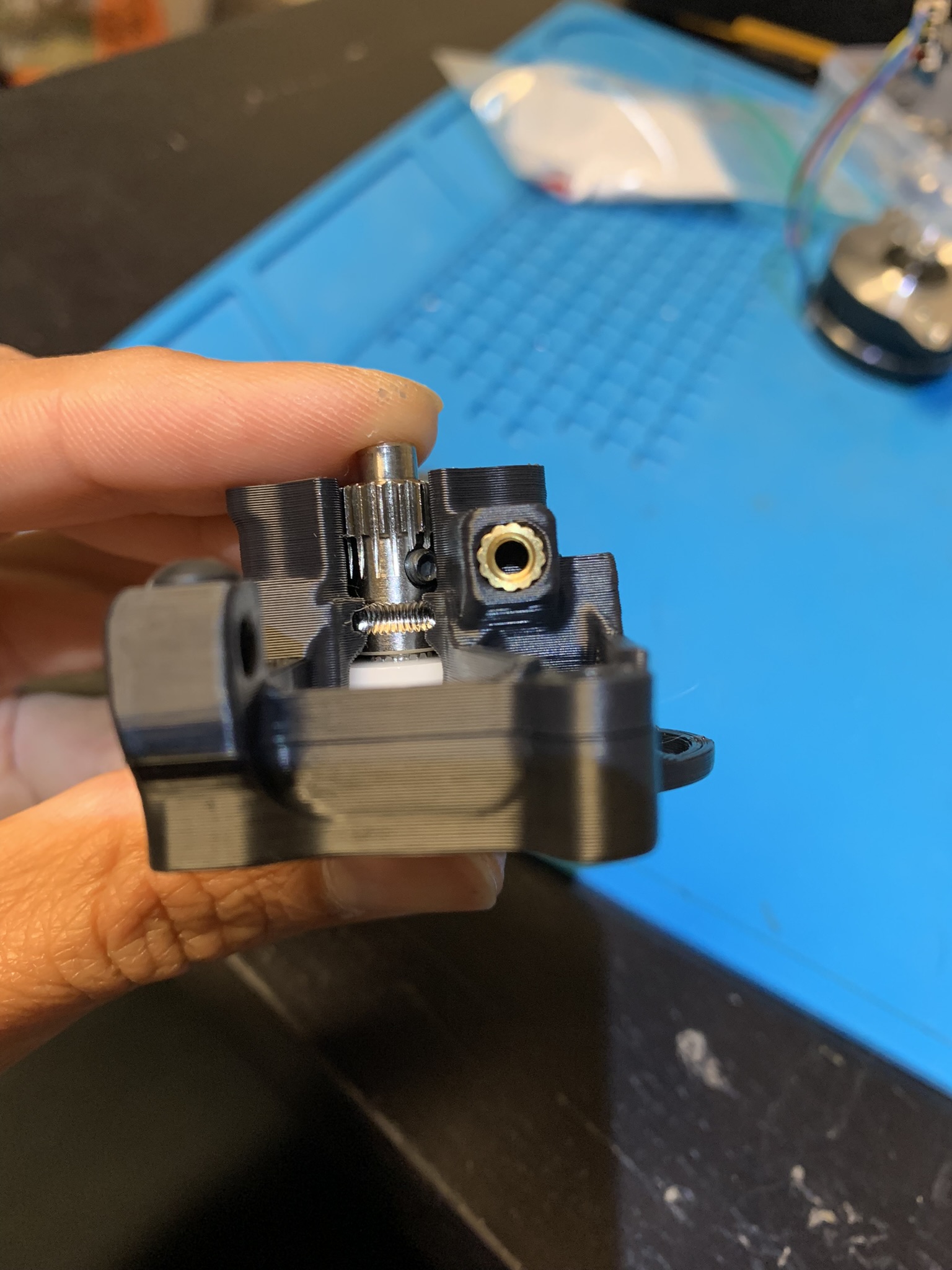
Figure 44: Drive gear placed onto drive shaft
Insert the needle bearings into the idler gear and place it on the idler drive shaft.
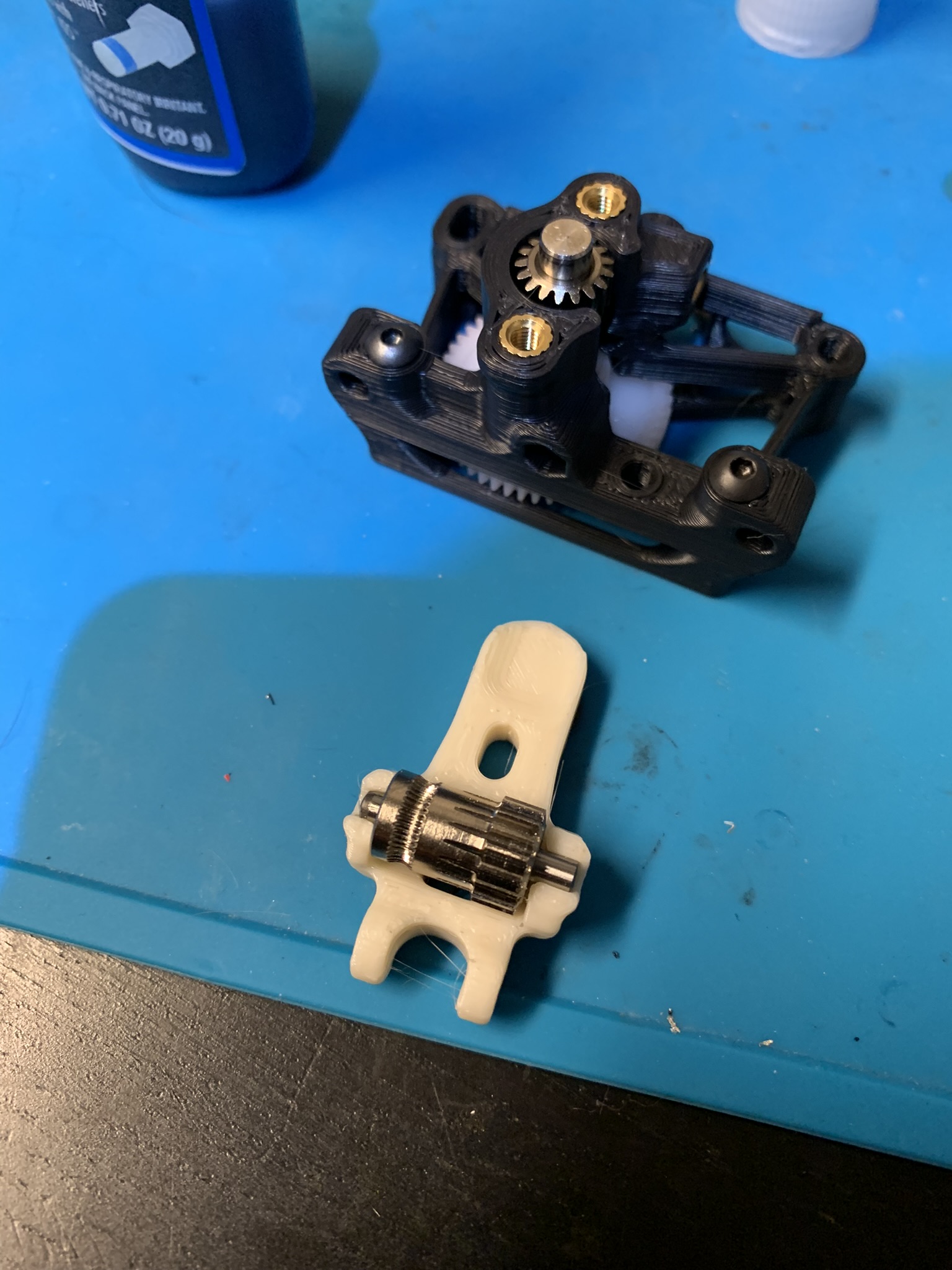
Figure 45: Idler gear installed
Insert the idler pivot shaft into the idler. Roughly center the idler on the shaft.
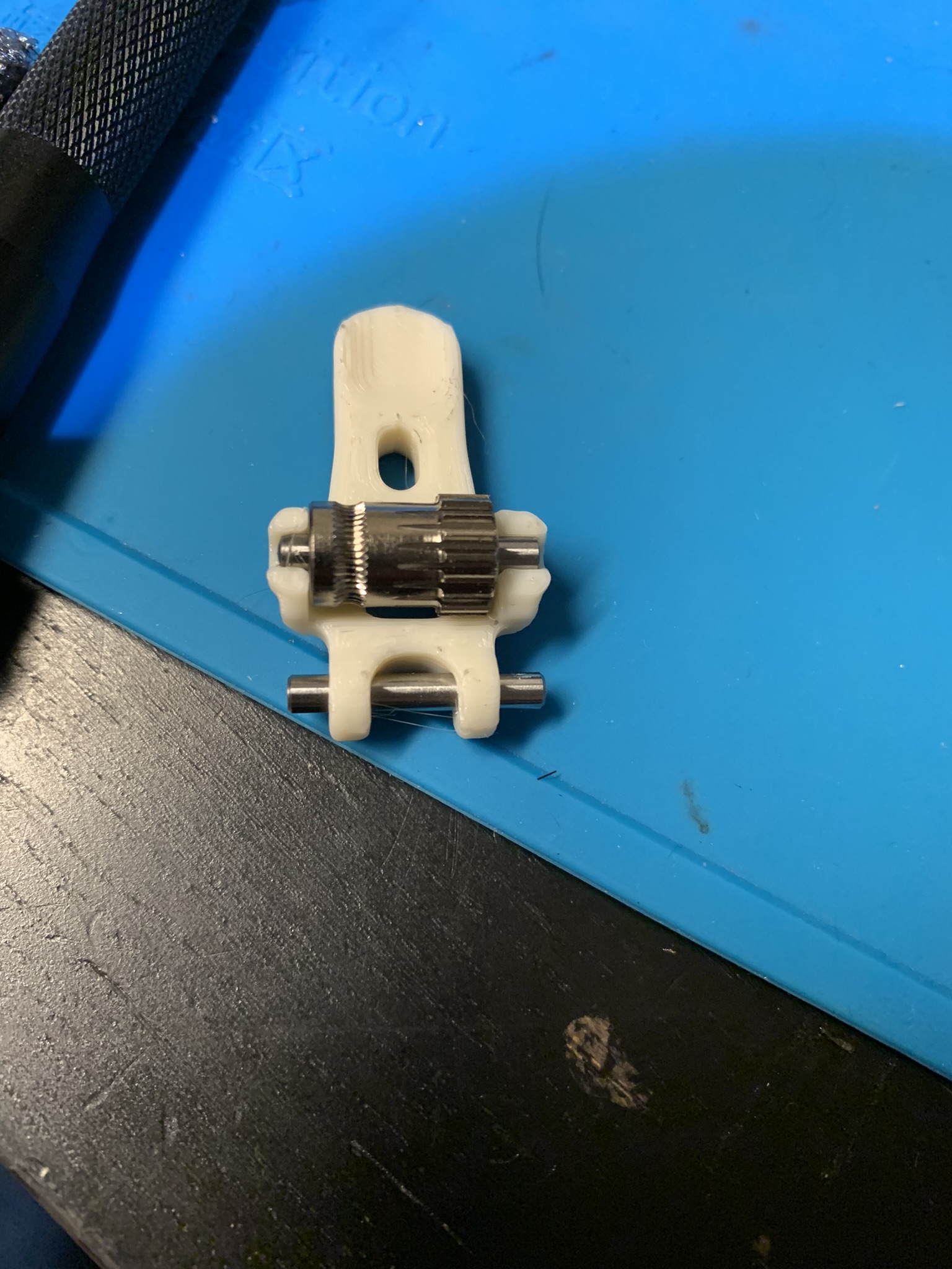
Figure 46: Idler gear installed
Insert the idler into the main housing.
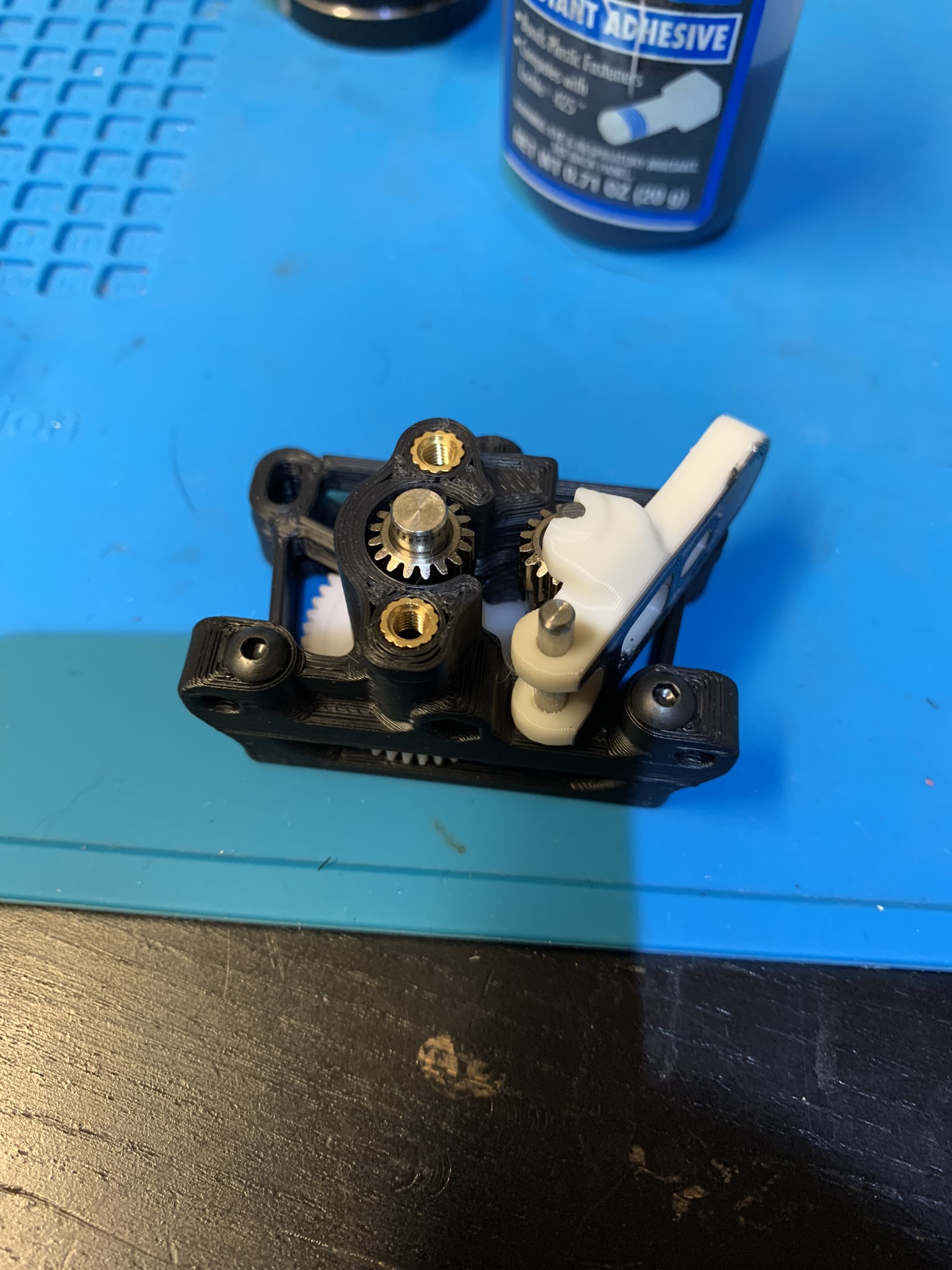
Figure 47: Idler installed into main housing
Place a bearing into the front housing.
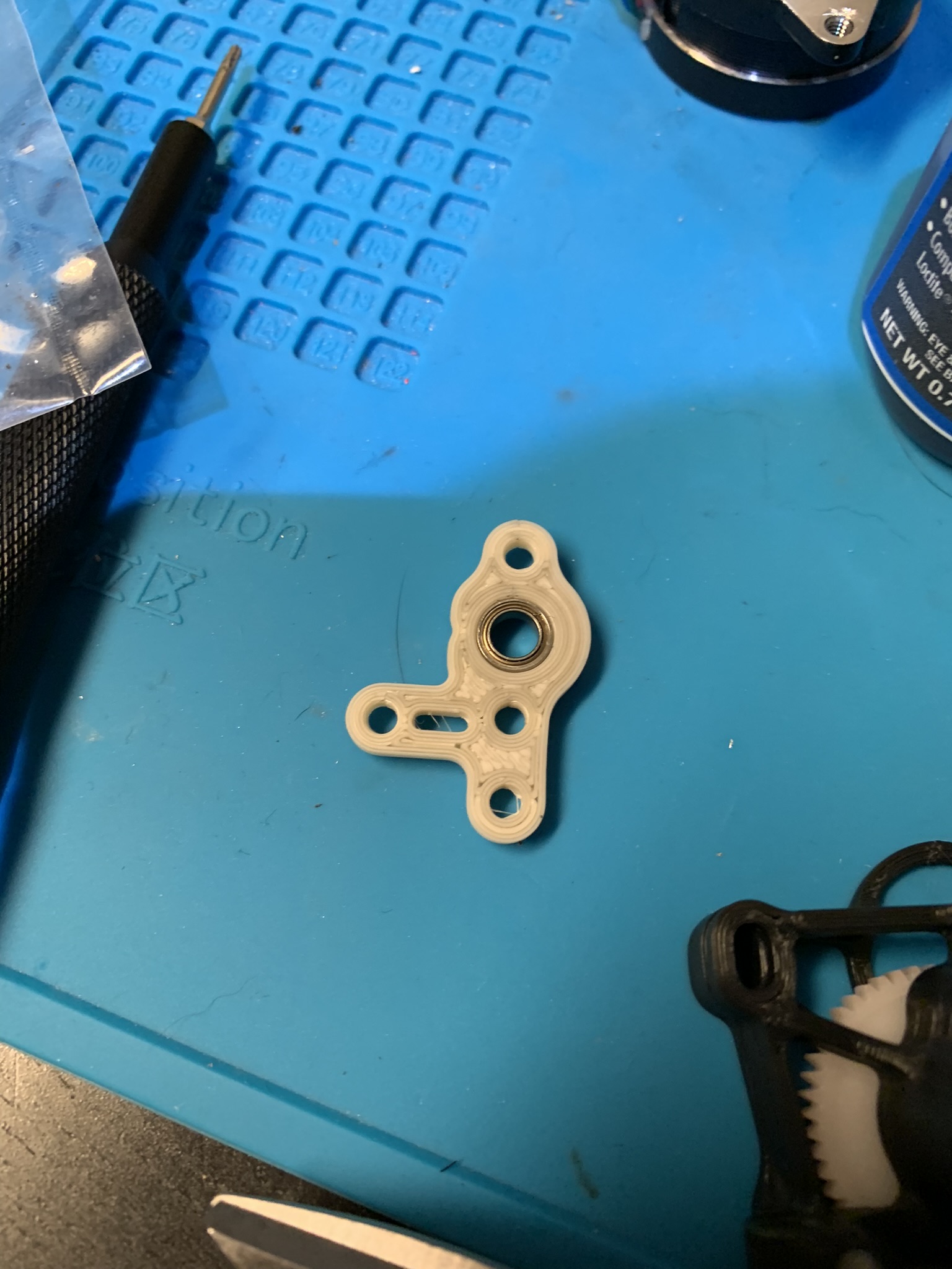
Figure 48: Bearing installed into front housing
Install the front housing onto the main housing and bolt it in using 2x M3x8 BHCS.
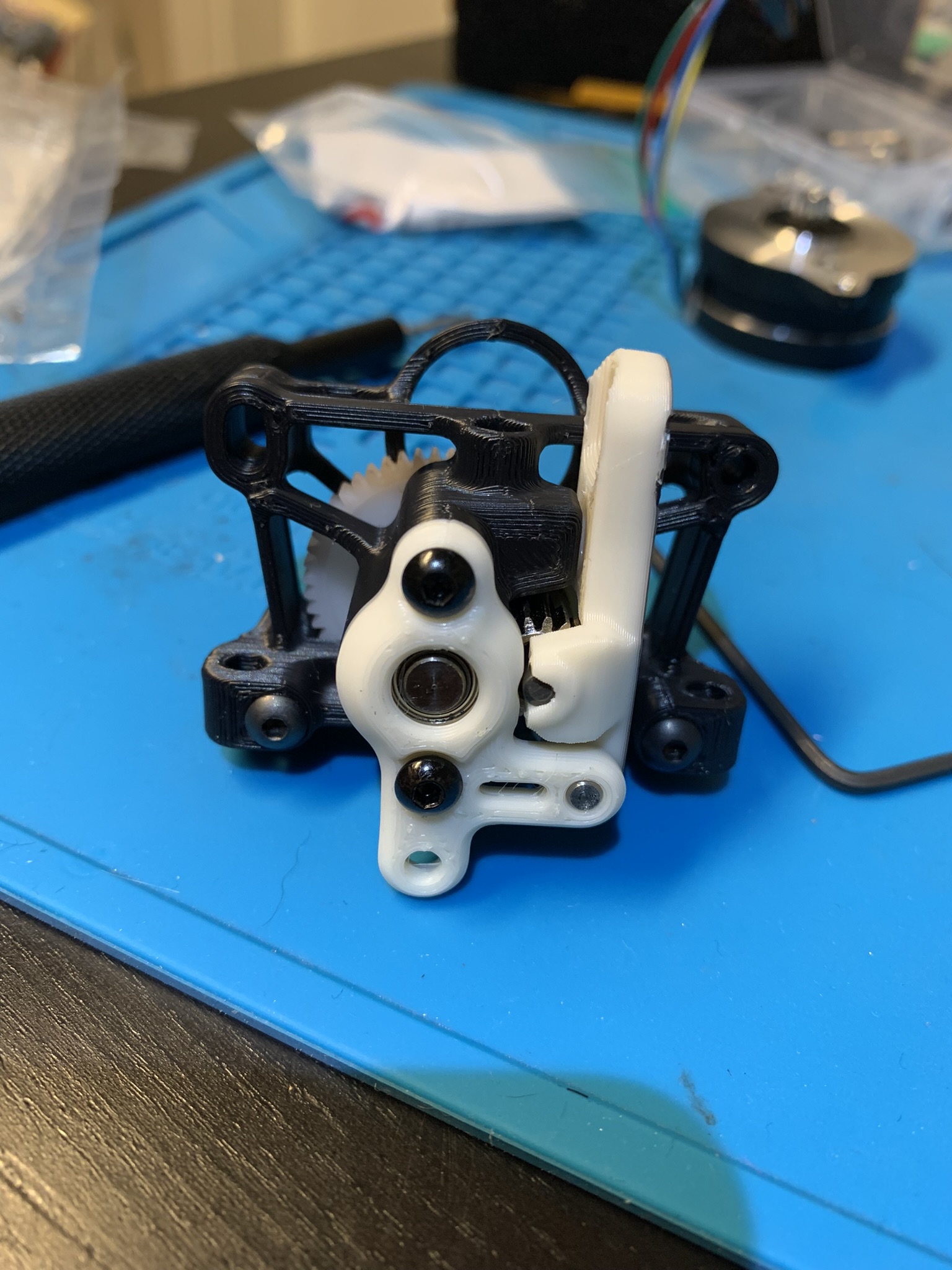
Figure 49: Front housing attached to main housing
Attach your motor to the rest of your assembly using 2x M3x16 BHCS. Keep the right bolt loose and rotate the motor until the motor’s gear and the main drive gear are meshed but not crushing each other, then tighten both bolts. Insert the spring and tensioner screw through the hole in the idler and screw it into the main housing.
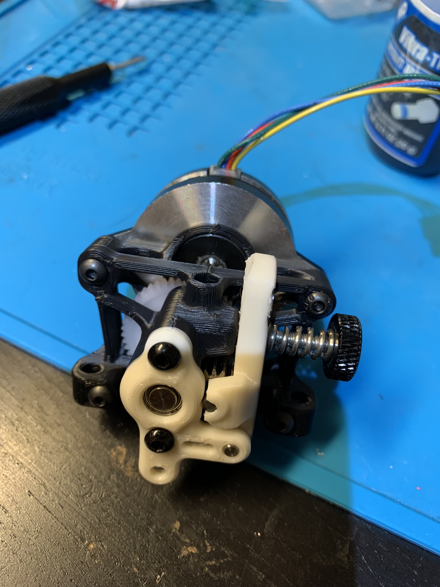
Figure 50: Sherpa mini, assembled
Installation
For mosquito hotends, there’s a jig in the K2 repo for cutting a bowden tube to the exact length needed so that it will be flush with the bottom of any supported extruder and the top of the mosquito. I used it to cut mine to the right length
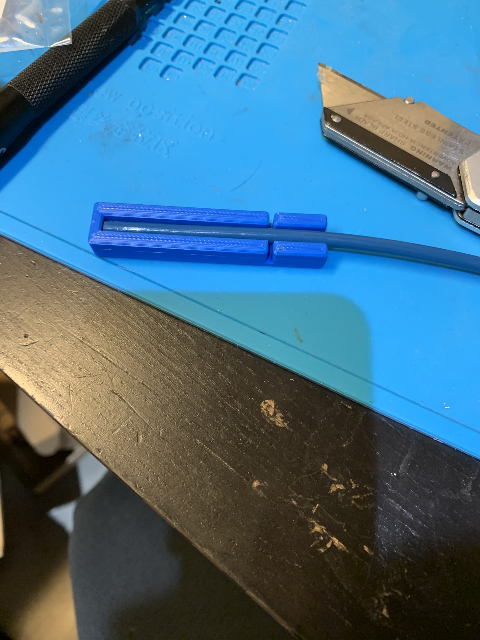
Figure 51: Cutting a bowden tube to the right length using printed jig
For other hotends, you can use a calliper to measure the length needed. The idea is to constrain the filament path from the extruder to the hotend. Once you have a tube of the right length, insert it into the toolhead
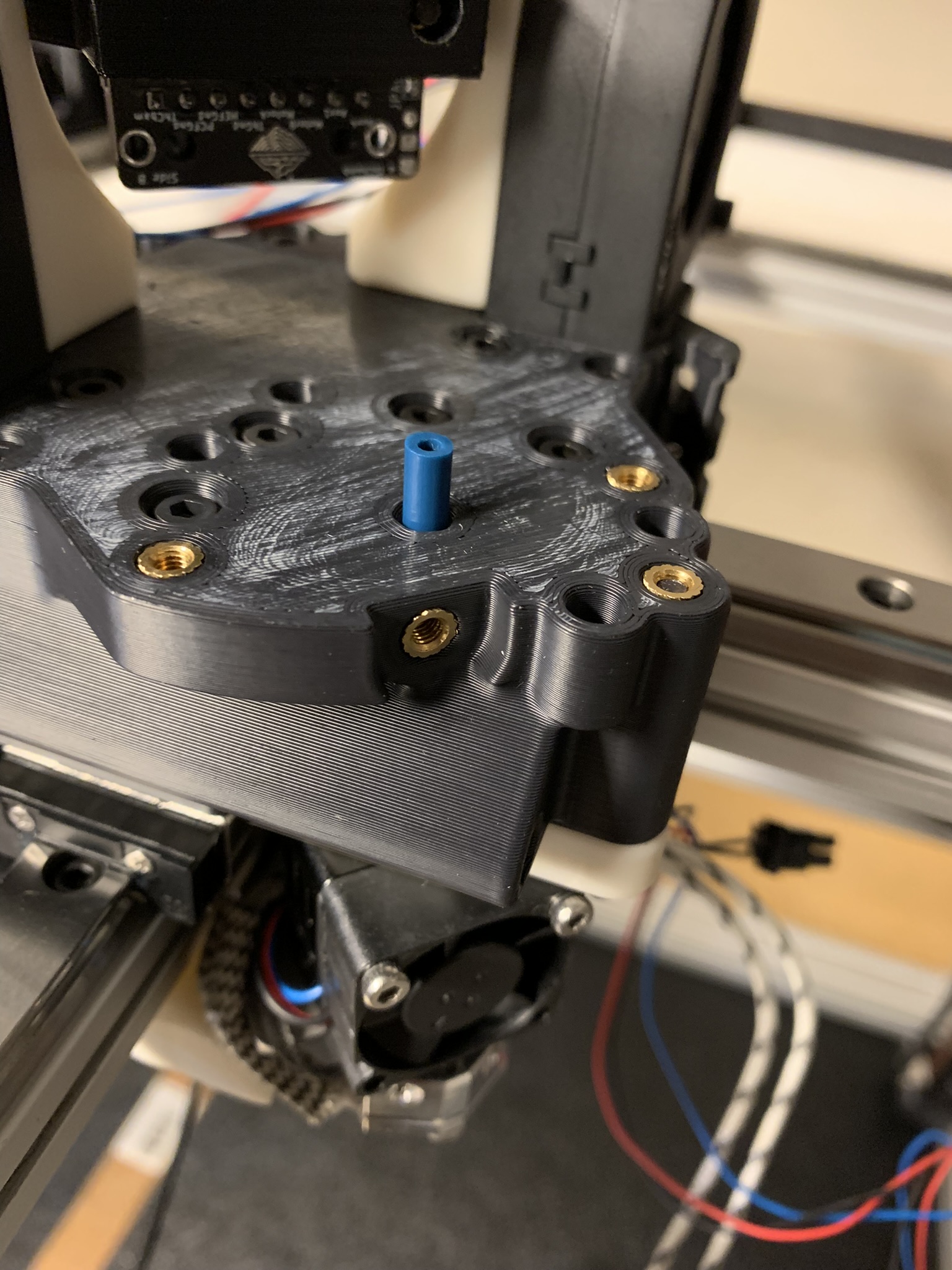
Figure 52: Bowden tube inserted into the toolhead
Align the sherpa so that the other end of the tube goes into it, and place it on the toolhead. Bolt it loosely using 2x M3x10 SHCS on either side. We’ll add the front bolt later.
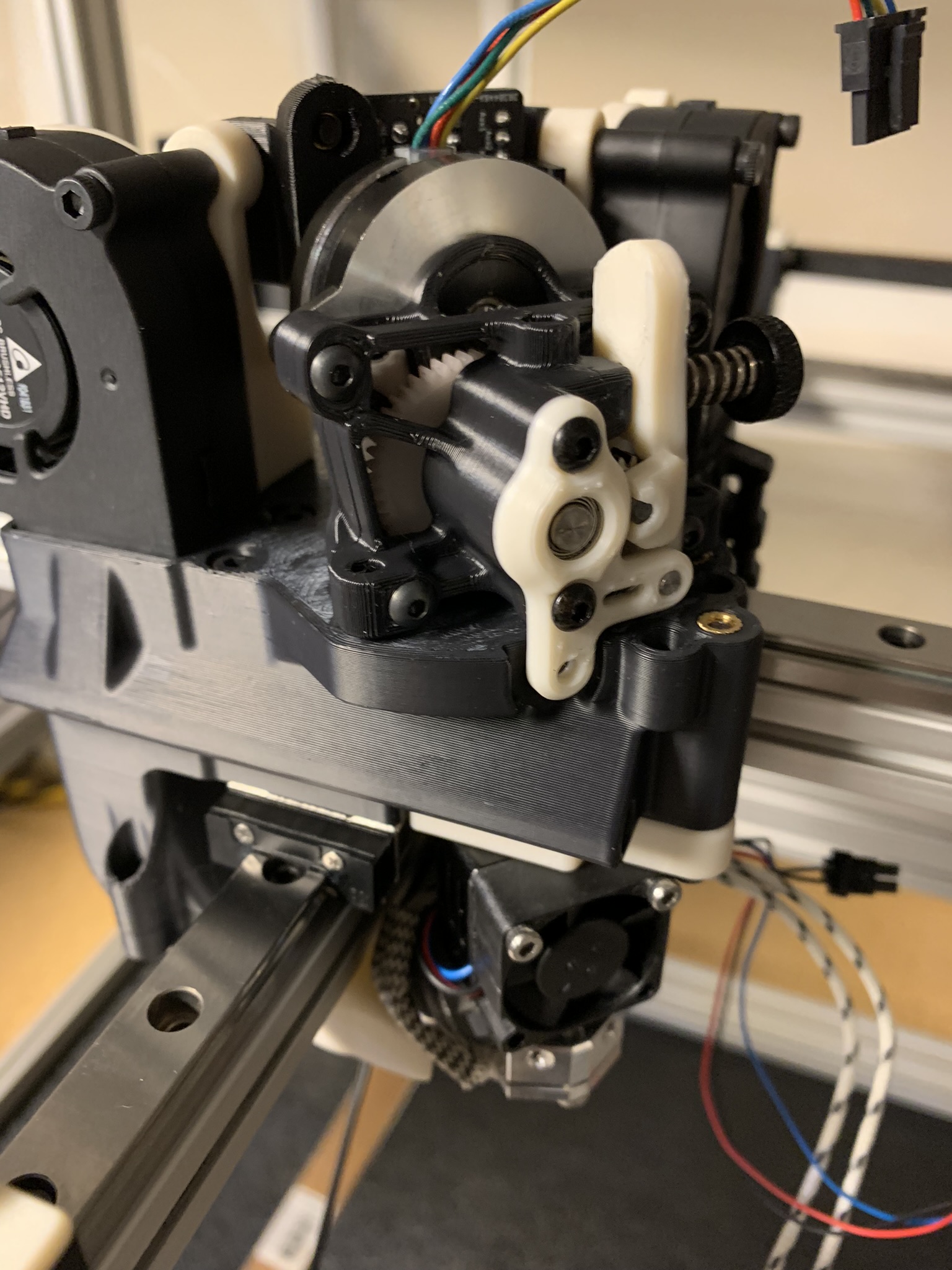
Figure 53: Sherpa attached to the toolhead
Feed some filament all the way through the extruder to the hotend. You should feel some tension from the extruder but no snags.
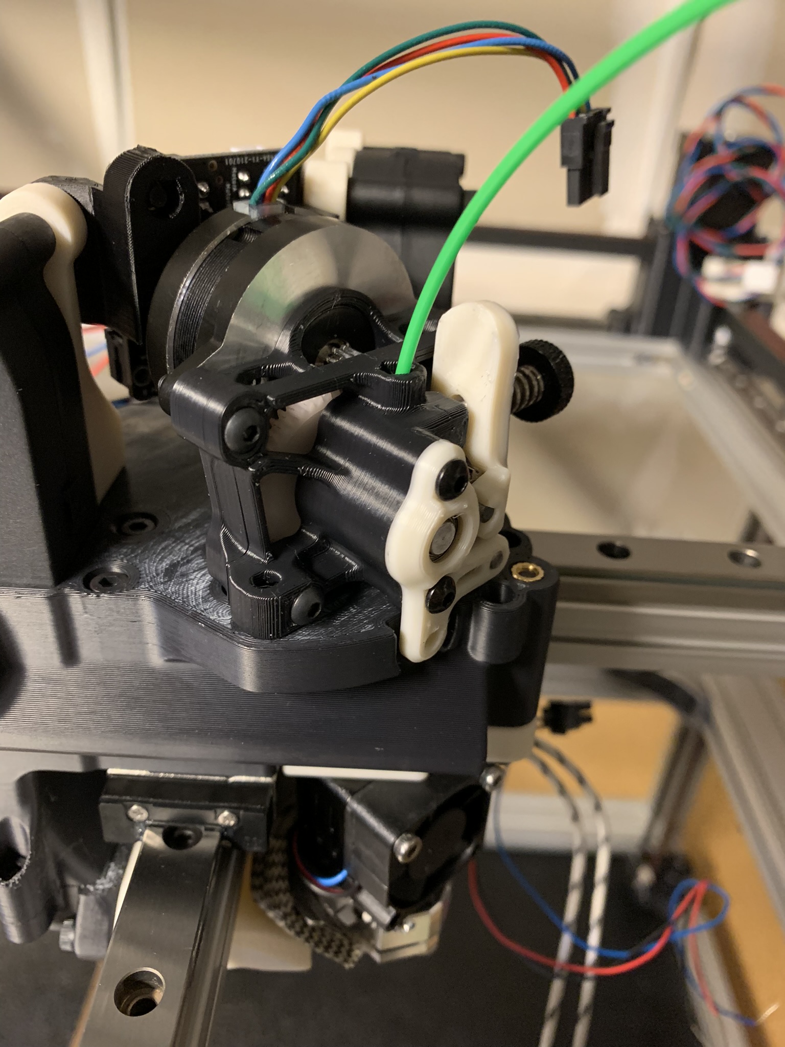
Figure 54: Filament fed into the extruder and toolhead
Take the filament back out and hold it outside the toolhead to verify that the length fed is roughly equal to the distance from the top of your extruder to the top of your nozzle
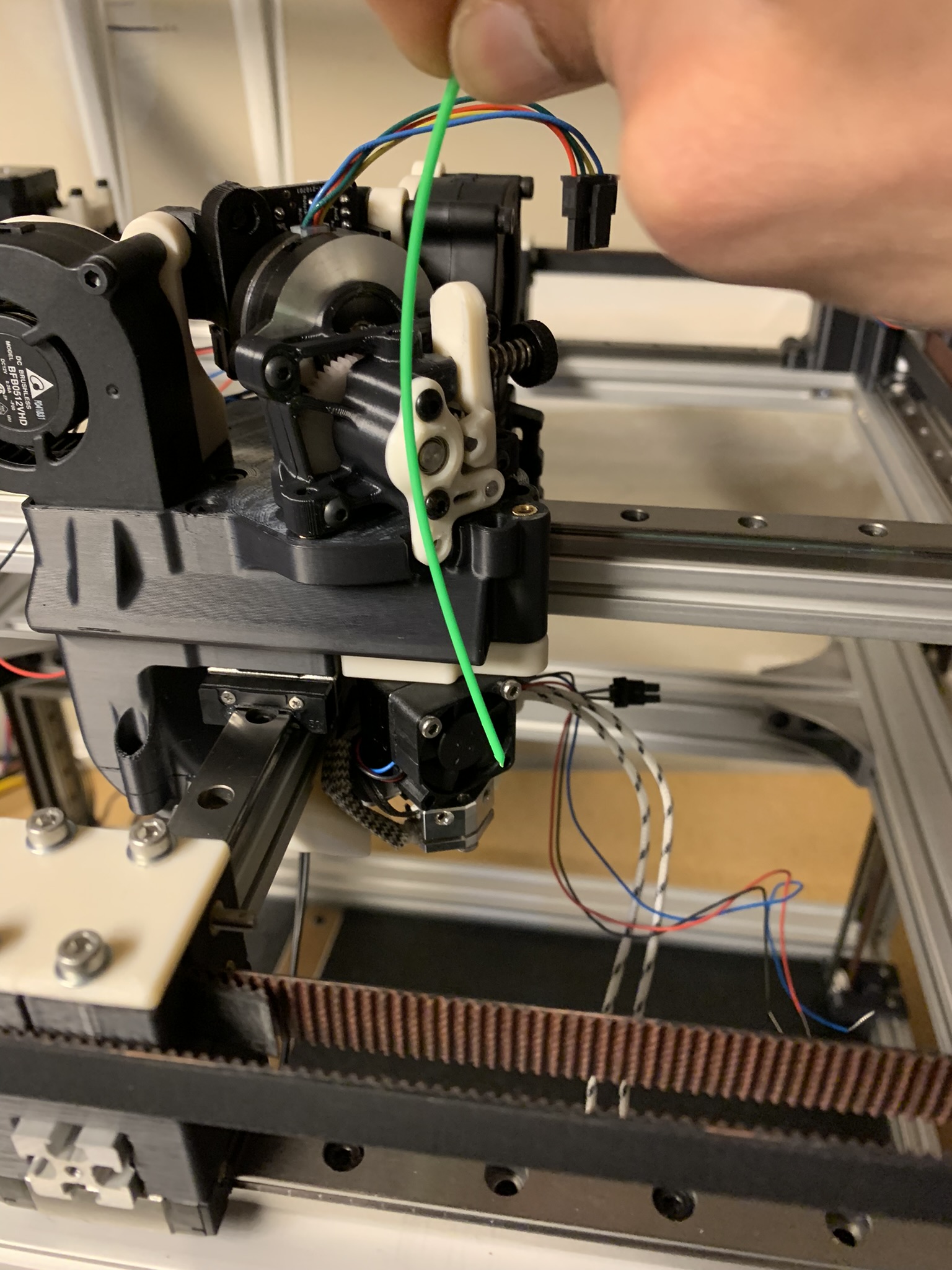
Figure 55: Length of filament fed into the extruder and toolhead
If yours is shorter, figure out where it’s getting stuck. The most likely cause is the hotend mount being off center. Loosen the bolts holding it place and wiggle it a bit to see if you can get the filament to go through, then tighten it back up.
Once you’re done, take the extruder back off so that you have access to the 8x bolts holding the toolhead to the cross rail carriages. We need to home the printer before tightening those, so the next post will cover the electronics backpack.